Tektronix 310 and 310A
6/19/17: Years ago I purchased a sparkfun o-clock thingy. It works but I didn’t take to it because the roman 4 is IIII instead of IV and things like that irritate me. The blurb on the website that I bought it from acknowledged this issue and stated that they would issue a code fix. However, when I tackled them about it, I was told that IIII is correct! In other words, they couldn’t be bothered.
I have sold the two 310A scopes and the other day, my mind wandered to the 310 and the thingy. An issue is that the X channel has insufficient gain and the image is mirrored, that is, electrically inverted. So, I decided to add a gain stage between the external X input CF and the X amp, this would also correct the polarity for the thingy. Here’s what I did: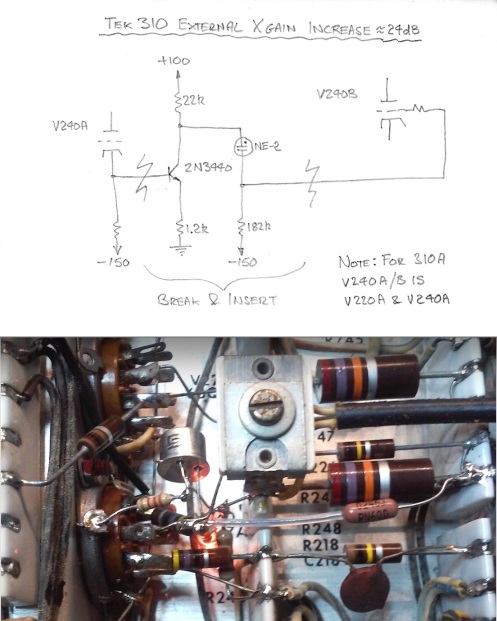
The neon is a simple way to preserve the DC coupling, you can just spot it glowing under the 2N3440 above. The negative supply allows a large enough resistor such that to all intents and purposes, at the signal swings involved (around 10VPP), the neon is operating under constant current conditions. I’m not going to show a picture of the result, you’ve seen them I’m sure. I may order a better thingy that does display a proper roman 4. It is necessary to adjust the X position when switching from internal to external but that was already the case.
 With the 310 design, Tektronix brought true laboratory accuracy to the portable oscilloscope. The picture shows my restored 310 serial number 1318, displaying 1 and 5µS markers from a Tek 180A temperature stabilised crystal controlled marker generator. I.B.M. had asked for a high performance, light weight portable scope to service their computers. Frank Hood made some suggestions as to the building of such an instrument and was assigned as project engineer to build a working model.
The design featured a clever DC coupled unblanking solution created by John Kobbe and the precision wide-band sweep generator of Dick Ropiequet* that for the first time, permitted time calibration. Appropriately the terminology “Time-Base” was adopted. (This terminology is sometimes inappropriately applied to repetitive sweep generators which cannot support time calibration.) Previous to this circuit, Tektronix individually engraved the fine sweep speed control according to sweep rate measurements made during final production testing. (You may see this if you go to the 511A page on this blog.) The Ropiequet circuit permitted the use of simple, stable and repeatable adjustments made during final testing together with standard sweep controls to indicate the sweep speeds in terms of time/division, e.g. mS/cm. An essential element of this circuit was a calibrated X-amplifier that also included an accurate X5 magnifier. (There is a more complete description of the Ropiequet circuit on the 535 Model page of this blog.) This technology, together with fully regulated power supplies, a regulated HF CRT supply and an internal amplitude calibrator that provided a square-wave of accurately known amplitude stepped in 1, 2, 5 ranges, formed the quintessential Tektronix oscilloscope of the era, one that set the standard for laboratory oscilloscopes. These elements were replicated not only in most other Tektronix instruments but emulated in function, if not in detail, by all reputable manufacturers.
* Dick Ropiequet came up with his sweep circuit originally for the model 315 oscilloscope.
By 1954 the engineering model met with the approval of I.B.M. and production was started as the model 310. This instrument was initially manufactured both under the Tektronix name and that of I.B.M. Being a specialized instrument, the people at Tektronix did not expect the sales to be large; they were wrong, 10s of thousands of the 310 and the 310A were sold before it was discontinued in 1971, a 16 year production run! I acknowledge vintageTEK.org as the source of the historical information provided here.
The 310 featured the first foray Tektronix made into etched circuit boards that were used for the HV supply and the Y pre-amplifier. The rest of the circuits were constructed using the brilliant and proven Tektronix ceramic strip technology (due to Tektronix employee Dick Goodfellow, who was interested in ceramics). Unfortunately, the reliability was poor (or at least, poor by Tektronix standards) and the instrument was re-packaged using the (now) well-known ceramic strip technology for all the circuits; it was re-issued as the 310A.
Here is one side of the Y pre-amp board:

Here is the HV supply showing several of the leaky paper-in-oil caps that I replaced:

The Y response of 90 nS brings a bandwidth of DC to 4MHz with deflection factors ranging from 10 mv/div to 50 v/div in twelve 1, 2, 5 stepped ranges.
The X axis is served by a triggered true time-base as discussed above. A feature of this design is that the (Schmitt) trigger can be switched into a low speed (circa 50Hz) astable “automatic” mode that drives the time-base thereby providing a baseline in the absence of a signal; when a signal is applied, the trigger responds as a bi-stable to the signal. The sweep speed ranges from 0.5 s/div to 500 nS/div in eighteen 1, 2, 5 ranges. A X5 magnifier permits the maximum speed to be increased to 100 nS/div.
The construction is truly marvellous, utilising a clever fold-out design to provide a lot of mounting surface for the plethora of tubes and circuits in the small package. They managed to stuff 30 valves plus the 3WPx CRT into a envelope measuring just 6.75 x 10 x 17, weighing 23.5 lb. It is also provided with a temperature cut-out yet I have not experienced one of these units overheat, a huge testament of the ability of the Tektronix designers to manage the heat from the 30 valves in the compact package! Having said that, an optional “Fan base” was available, it was a wedge-shaped platform to stand the scope on that improved the viewing angle as well as containing a cooling fan. There is a multitude of detail electrical differences between the 310 and the 310A, perhaps the most notable being the use of 6U8s in the trigger amp and trigger circuits (in common with all early Tek scopes having the Ropietquet time-base).
The usual repairs were needed: Replacement of almost all the paper-in-oil caps. In particular, other than the HV caps, the hold-off cap for the slowest ranges was preventing the time-base from re-setting after a sweep; this is a common problem with valve Tektronix and HP ‘scopes. The electrolytics are OK; I disconnected them and tested each one by charging it from a bench power supply via a series resistor to ensure it could sustain its full rated voltage with low current draw. Once I had the scope powered up, every power rail was staying in regulation down to a line voltage of 105V except the 300V rail. This unit has selenium rectifiers; (I don’t replace or bypass these unless there is a functional problem such as failure of the following regulator to operate down to a line voltage of 105: Operate properly includes ripple rejection as well as regulated voltage.) I simply attached 4 UF4007 rectifier diodes to the existing rectifier for the 300V rail and included the Tektronix traditional 10Ω series “transformer saver” resistor. The triode section of the calibrator 6AN8 was dead and one of the X-amp 6BQ7s was weak causing a badly off-centre position control. (The 310 uses one 6BQ7 for each cathode follower / amplifier rather than having two cathode followers in one 6BQ7 driving two amplifiers in the second 6BQ7 which was adopted in the 310A re-design.) Another issue was that the 3.9M carbon resistor in series with the focus control was showing about double that resulting in the focus control being hard anti-clockwise. This fault is most likely an indication of a crack in the resistor rather than the usual aging related increase in resistance.
Tektronix recommends trying valves in the circuits to check whether they work or not rather than relying on a tube tester. I can attest to this; I spent many hours fiddling with the trigger. I had noticed that it did not auto-run properly and so started investigating. I tested many of the valves I had on hand and several tested very strongly but would not support both auto-run and trigger properly, in particular, I could not obtain repeatable triggering on small signals when switching the trigger polarity; the 310 design does not have an internal DC trigger level adjustment and so the trigger valve must not only be strong but also be very close to specification with regard to grid to cathode potential at cut-off in order to support both the auto-run and accurate trig level centering. I did eventually identify a valve that works in the circuit properly. The other job was to use “Deoxit” on every tube pin.
Here is the “parts kit” that resulted when I stripped the unit for washing. I usually use distilled water but I wanted to do this one in the sink under the hot tap so I removed the power and HV transformers:

Here is a view showing the replacement HV caps (white jackets) and PSU regulator feedback caps (yellow jackets):

Here is the left side showing the Y-amplifier (above the CRT) and the X system (below the CRT):
")
Here is the right side showing the power supply and regulators:

And here it is opened up in all its glory!

Here are some pictures of the 310A, here seen displaying the internal calibrator:


Here is the right side closed:

Here is the left side:

The designers managed to sneak three valves in past the eyes of the bean counters (or in those days, maybe the bean counters did just that, count beans…..). The left-most valve is for the timebase hold-off circuit and other two 2 are the trigger bi-phase amplifier and Schmitt trigger shaper circuit:

Here are attempts to capture the drama of all those valves:


One of the three units I have would sometimes fail to display. It turned out that a heater solder-joint in one of the CRT pins had gone bad. I simply re-flowed both of them, that restored proper operation.

Great restorer, great job.
Beautiful!!! This is one of the best looking scopes Tek ever made.
I have one to it works great but there’s a 60Hz ripple at the left side of the line and I can see the beam sweep back is that normal
You haven’t given me much to go on however, the beam should be cut off except when sweeping unless on auto in which case the timebase will free-run. The retrace should never be visible.
There should be no ripple visible, the exception being if the Y attenuator is set to the highest sensitivity, 60Hz energy can be picked up at the input socket. If the ripple is still present when the sensitivity is reduced to less than .05V/cm (i.e. out of the ac only ranges), then it is likely that V401 and V408 need replacing. There are many Tektronix 6AU6 matched pairs still available on Ebay.
Also, there should be a shield mounted at the front of the swing-out chassis that shields the Y attenuator when the scope is closed. This shield is sometimes missing. You can see it in one of my pictures.
If you have another scope, check the -150, +100 and +300V regulated supplies for ripple. One or more of the 12B4 series pass tubes may be tired. Since you have ripple at the left only, I suspect the supplies since the current draw impulse when the timebase fires may causing one or more of the regulators to drop out for a brief moment. Getting a laboratory grade instrument of any kind to work as designed must always start with the power supplies.
If you are no familiar with the operation of a triggered oscilloscope, try searching for a triggered scope simulator / tutorial. Make sure it is for an analogue scope, not a digital one.
What is a good place to find a 3wp11 or a 3wp1 crt? Tim kc2ttt
I would keep and eye out on abay.
Thanks Richard, your site has really helped me restore my 310 scope, all HV caps replaced in the manner you suggested. I also had to disassemble the CRT socket and resolder the wires… that was quite a chore but now I have a great scope that I can use in my lab. The repair of this 310 has vexed me for several years and only now with your terrific advise is it done and happily working.
That’s wonderful Thomas, thanks for letting me know.
Richard