
This article replaces a previous one. The back story is that I am a “senior citizen” piano student working for the ABRSM Grade 8 exam (final). It’s a major challenge at an age where not only cerebral memory but muscle memory is fragile and I’d practised myself pretty much to a stand still. I needed something to chew on and having acquired the major parts for a radio years ago, decided to build one and this is the result.
This was a good opportunity to learn a little about RF tube electronics and this is the first radio that I have constructed. My previous RF experience is limited to restoring a Bush AC91 table radio, a Halicrafters SX-71 receiver and a Heathkit SB-2 transceiver plus various items of radio specific test equipment. The broadcast band is badly polluted by RFI, presumably coming from the proliferation of switched mode power supplies, computers and other broadband noise generators. The noise actually made attempting to use the radio annoying. I did a little research on the net and discovered the Tecsun tuneable broadcast loop antenna. It works extremely well. The trick is to scan the band slowly with the radio, following with the antenna tuning, rocking it gently to help pull in the transmissions. I am now mostly using it to listen to internet radio (largely BBC) using a FCC Code 15 legal AM transmitter that I built years ago, akin to tube era BlueTooth.
I think the way I’ll structure this article is to start with such features as it has, then lots of hopefully interesting pictures with some notes about construction and get into technical depth at the end. First some technical terms. Heterodyne is the term used for mixing two frequencies to get a sum or difference frequency. Superhet simply refers to this process at supersonic frequencies. A superhet radio is tuned into the desired receive frequency and presents this to a mixer or frequency changer. A “local” oscillator provides a second frequency that tracks the tuning of the receive frequency such that a constant difference frequency is available at the output of the mixer, this being referred to as an intermediate frequency, IF. The advantage is that the signal can then be amplified by a amplifier stage that is designed to operate at just one frequency and is thus equally effective across the entire band that the radio is designed to receive. AGC refers to Automatic Gain Control that helps to level the response of the radio to strong and weak signals. It also helps to compensate for the coming and going of the signal due to ionospheric activity. Detection refers to separating the audio signal from the AM intermediate frequency.
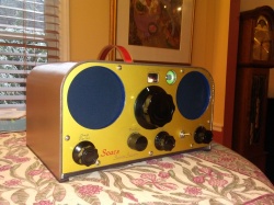
It is a five (valve or tube) plus one superhet, the plus one being the inclusion of a tuned RF stage having user variable gain on the front end. The coverage is 550 to 1600 kHz, known to the British as the medium wave. I also decided to include a magic eye for fun and with a tube rectifier, this accounts for the “Super Seven” moniker on the front. The superhet circuit is generic except, I split the AGC and detection circuits (the 6AT6 tube has two diodes) and provided an additional germanium diode, doubler fashion, in the AGC circuit to increase the available control voltage. The AGC may also be switched off and thus holding the radio at its maximum sensitivity. The other area where it departs from the norm is the output stage which is not only triode connected but uses cathode coupled negative feedback. There is so much gain that I was trying to lose some in the AF stages and it made sense to do this in a way that increases audio quality. The tube lineup is, 6BA6, 6BE6, 6BA6, 6AT6, 6AQ5, 5AR4, 6EC5.
So to the pictures somewhat in order of construction:
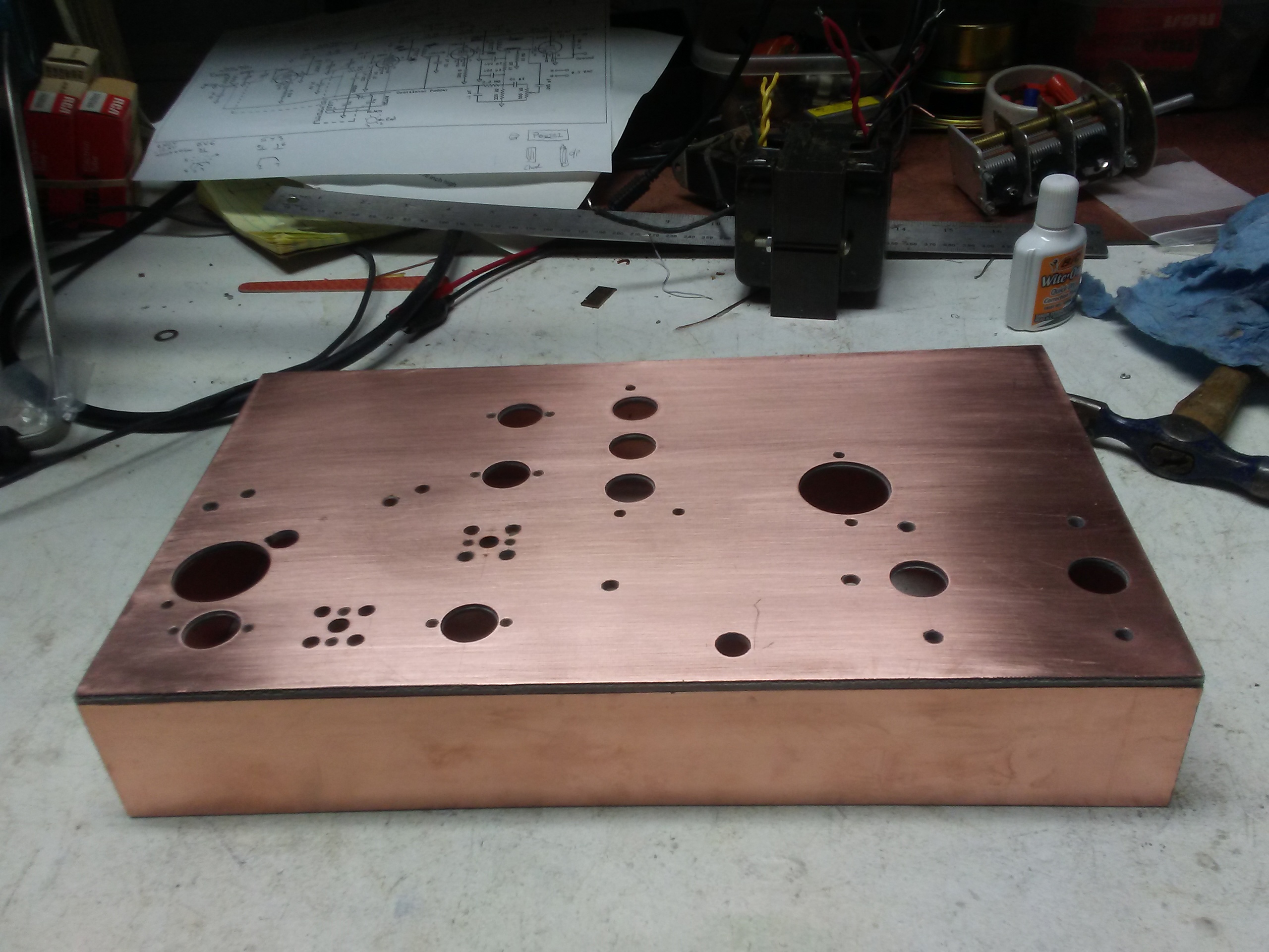
The chassis is made of 1/8th thick copper clad GRP, soldered together. I found my Hacko iron was powerful enough to run a fillet along the inside joints.
Here’s the bent plywood case and wood sub front panel:
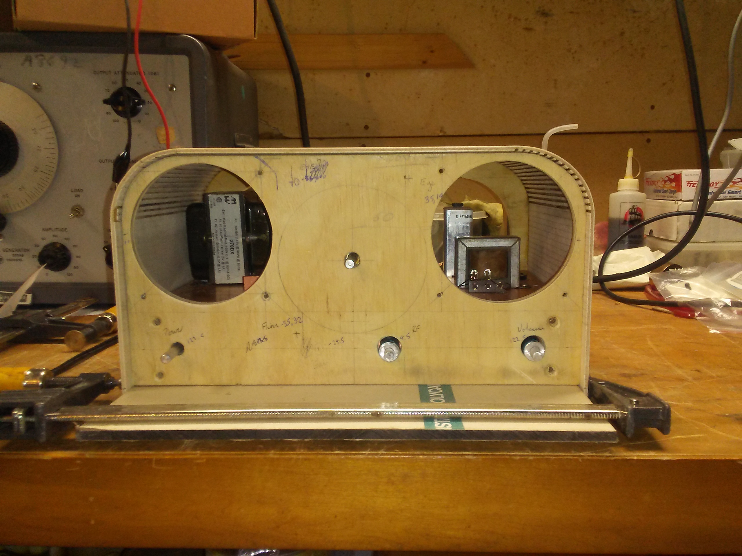
The case was made of 3mm plywood on a former. I cut kerfs using a pocket sized table saw from Harbor Freight to aid the bends. It is shown standing on a sheet of 1/4 lexan which became the base.
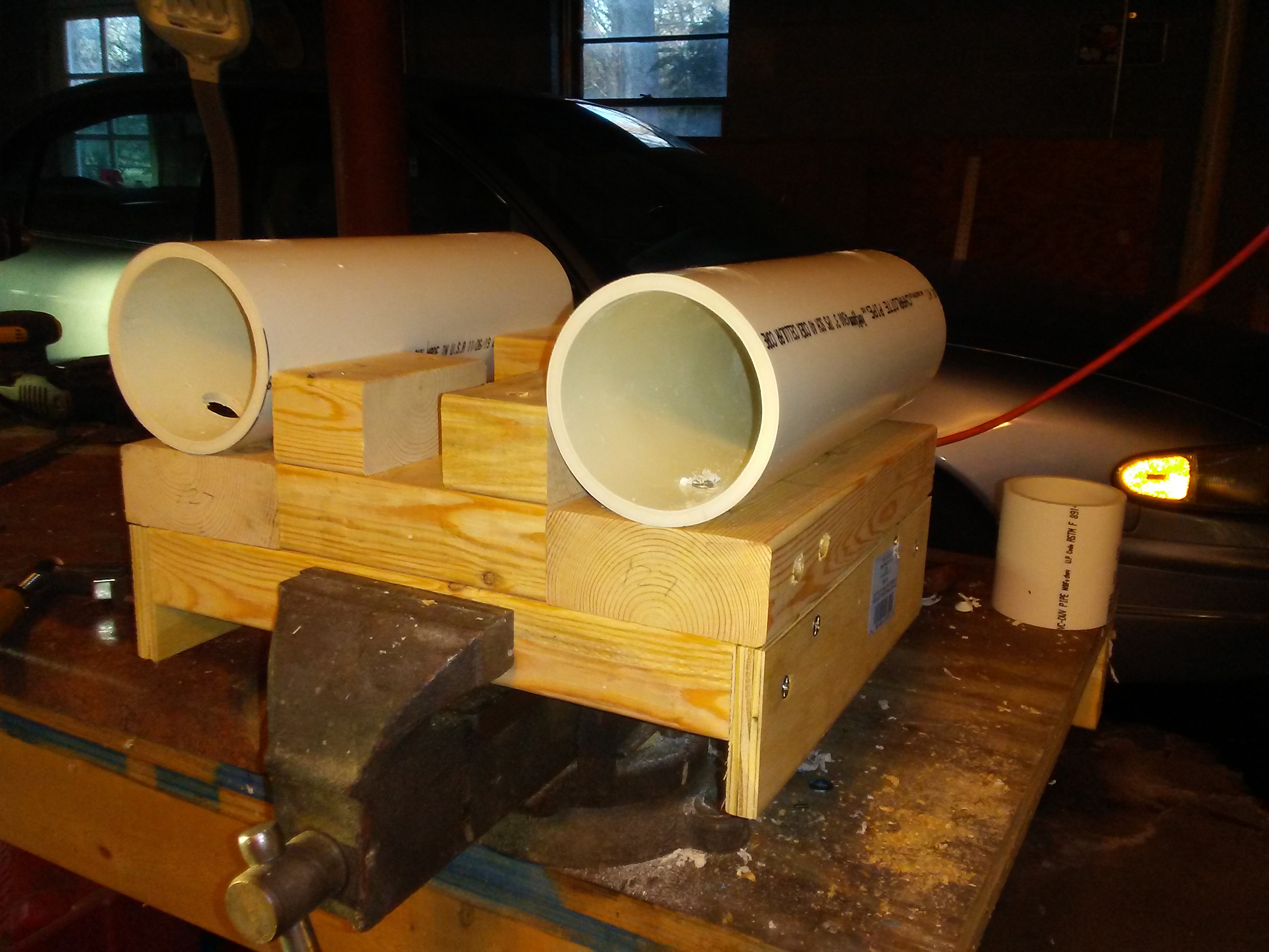
Trial kerf cutting: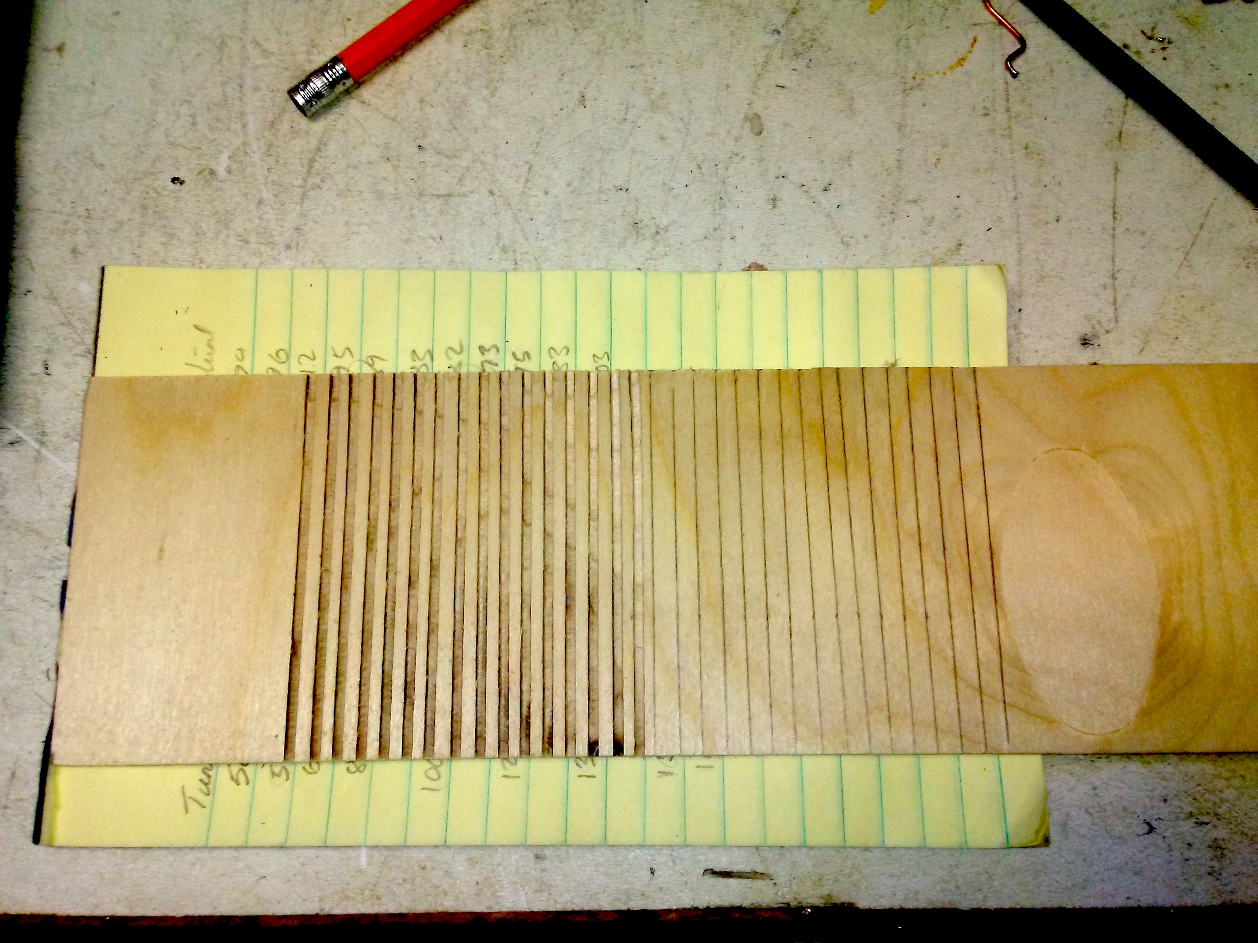
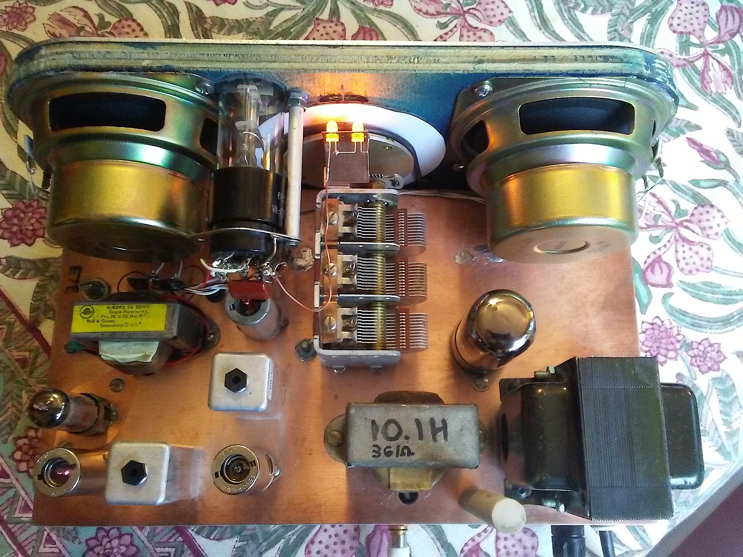
Here’s some details of the tuning drive and magic eye:
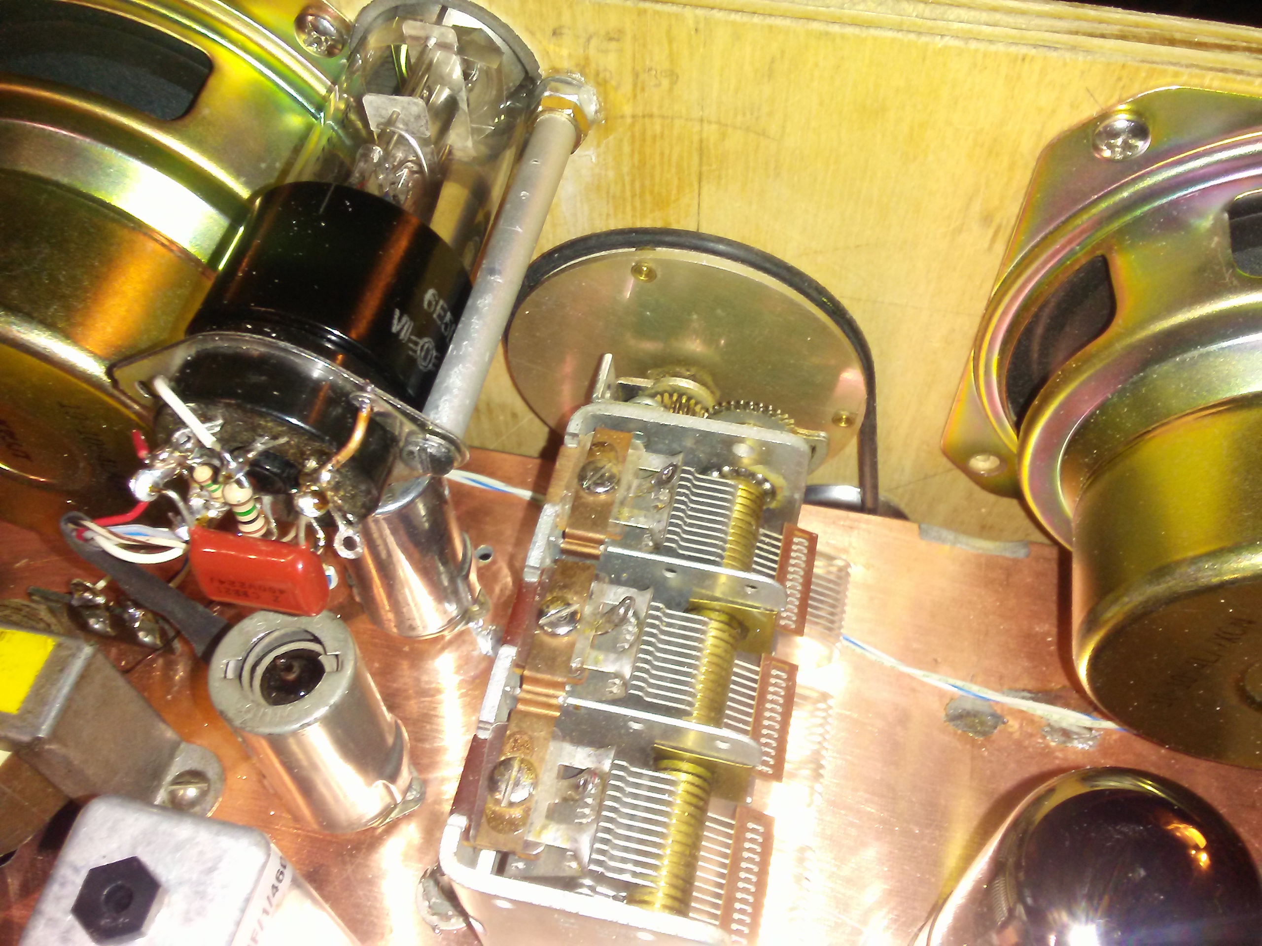
Slow drive and back light LEDS: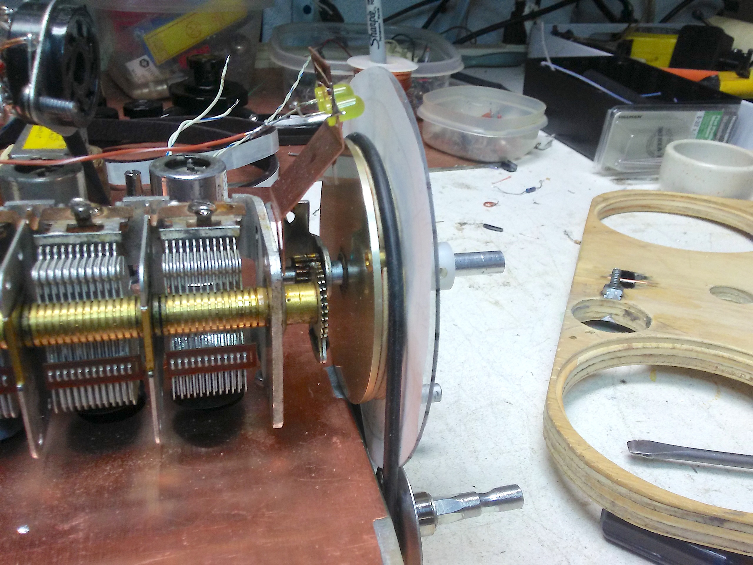
The slow drive spindle is an adapted Stanley quick drill chuck adaptor. I used this because it is rubber covered which helps to reduce slipping of the rather crude rubber O ring drive belt: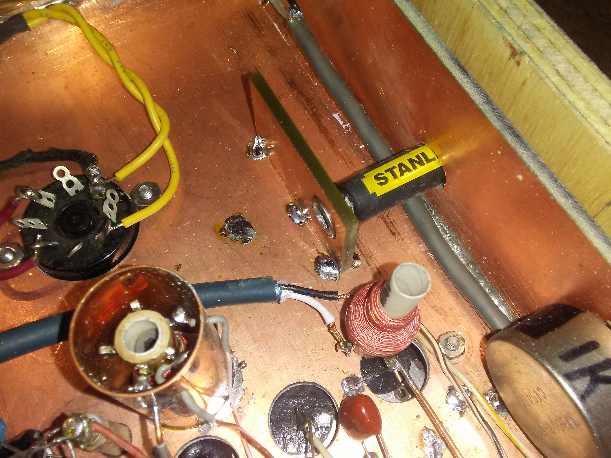
Initial calibration (more on this in the tech section):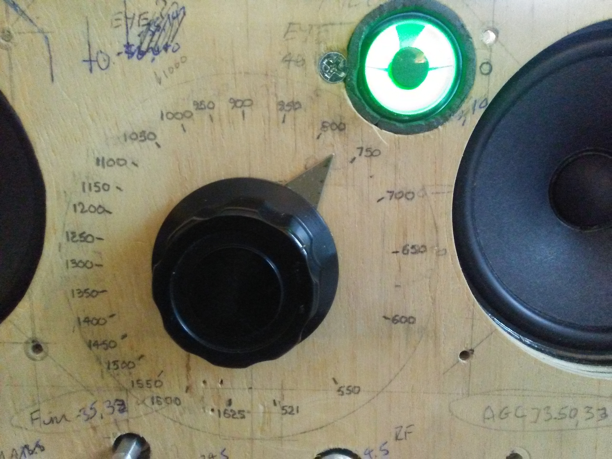
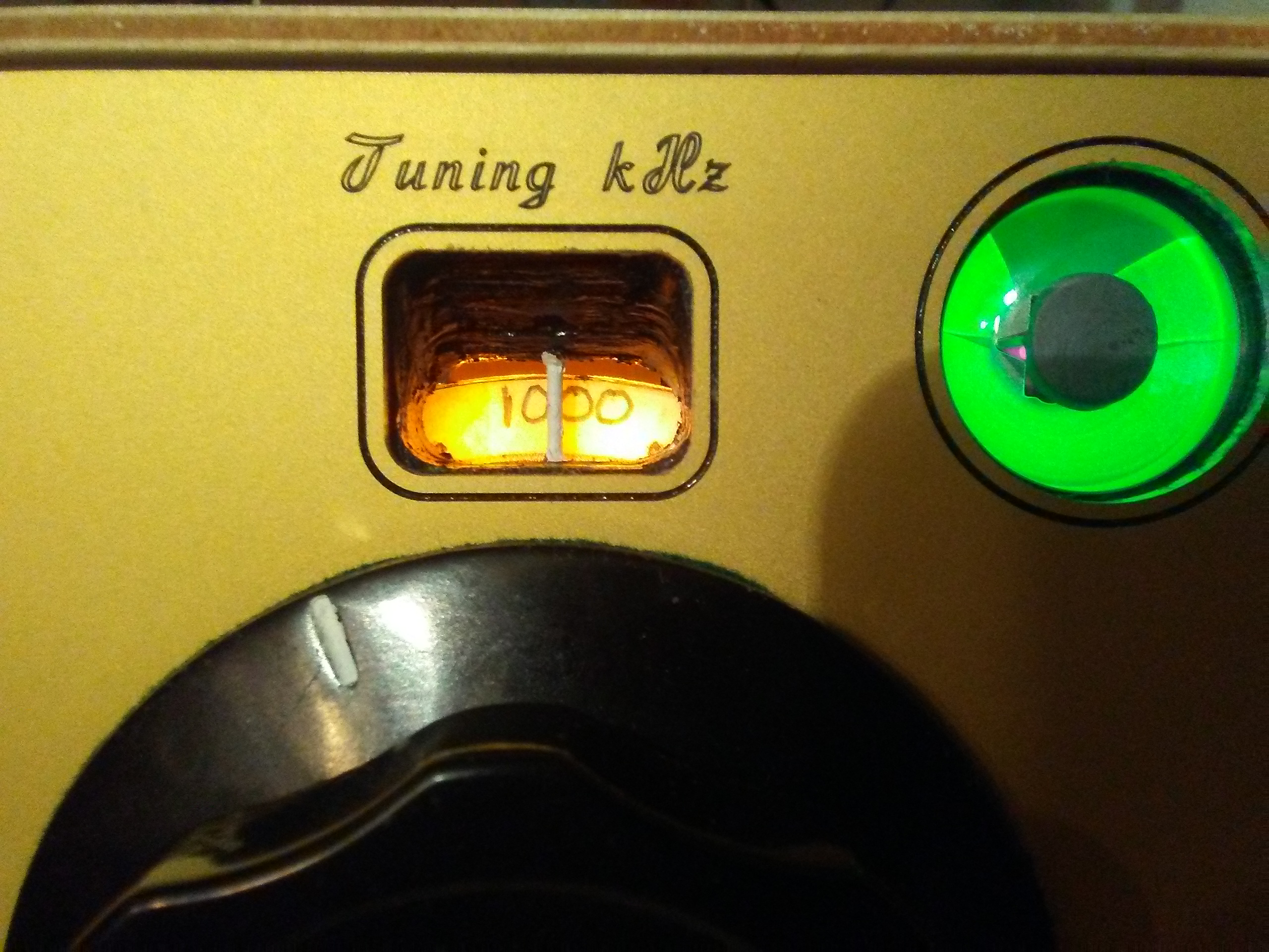
The final dial. The numbers appear behind a fixed cursor in a viewing port, pre WW2 style and are backlit. The dial itself is simply a disc of paper attached to an acrylic (I think) disc.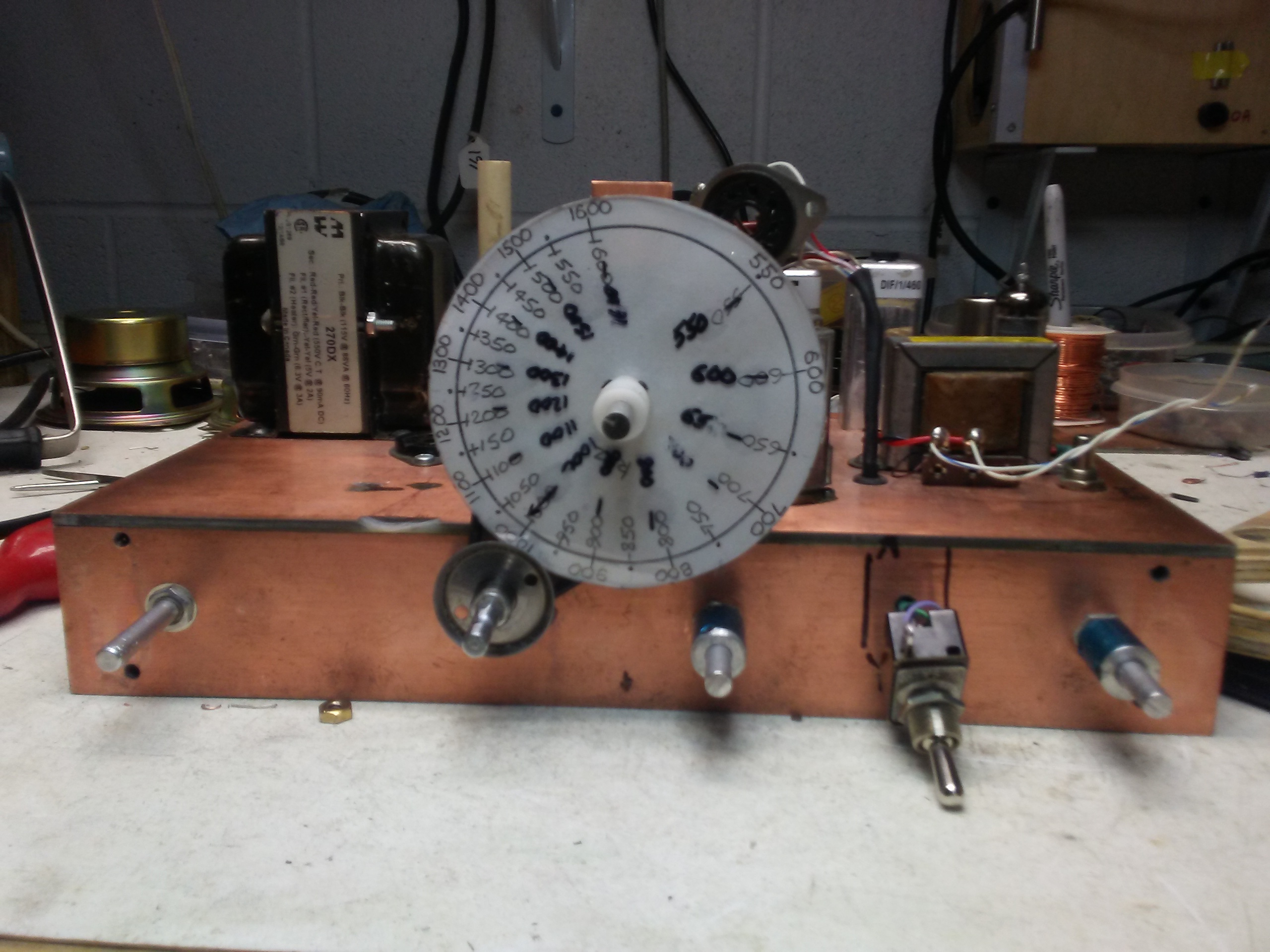
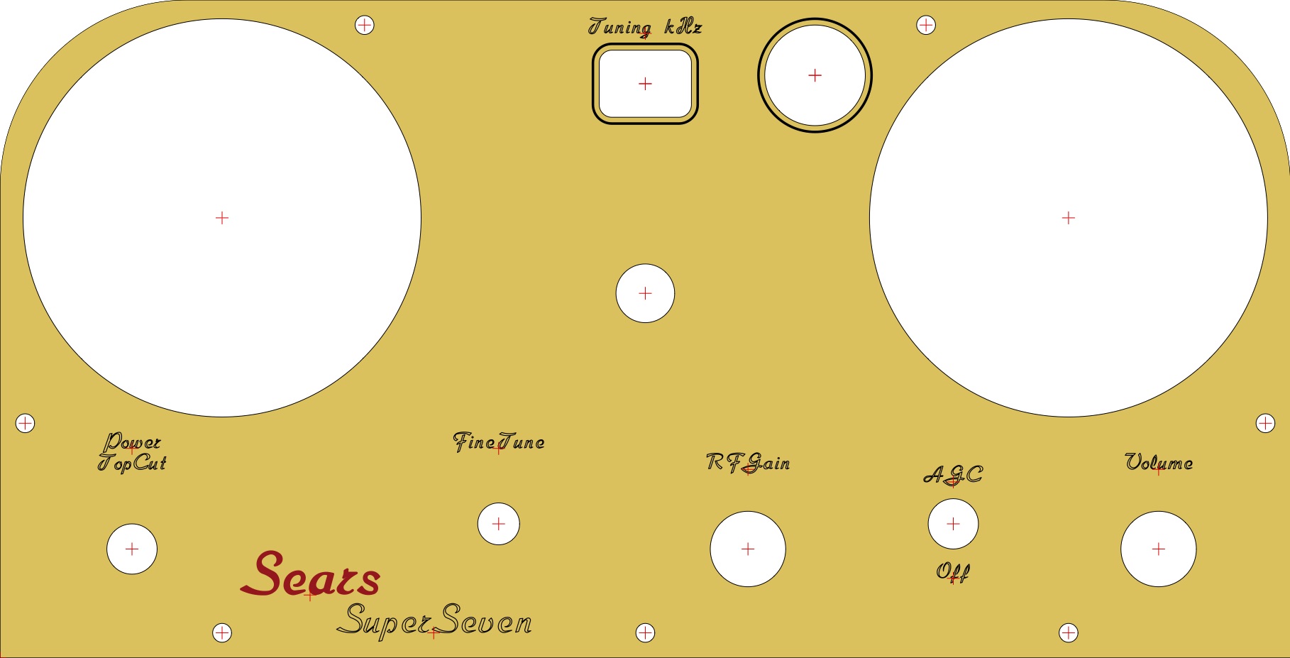
Here’s the design of the aluminium front panel, exported from the Front Panel Express design program:
And so it came together:

I affixed the schematic to the top which being hand drawn adds interest in my eyes.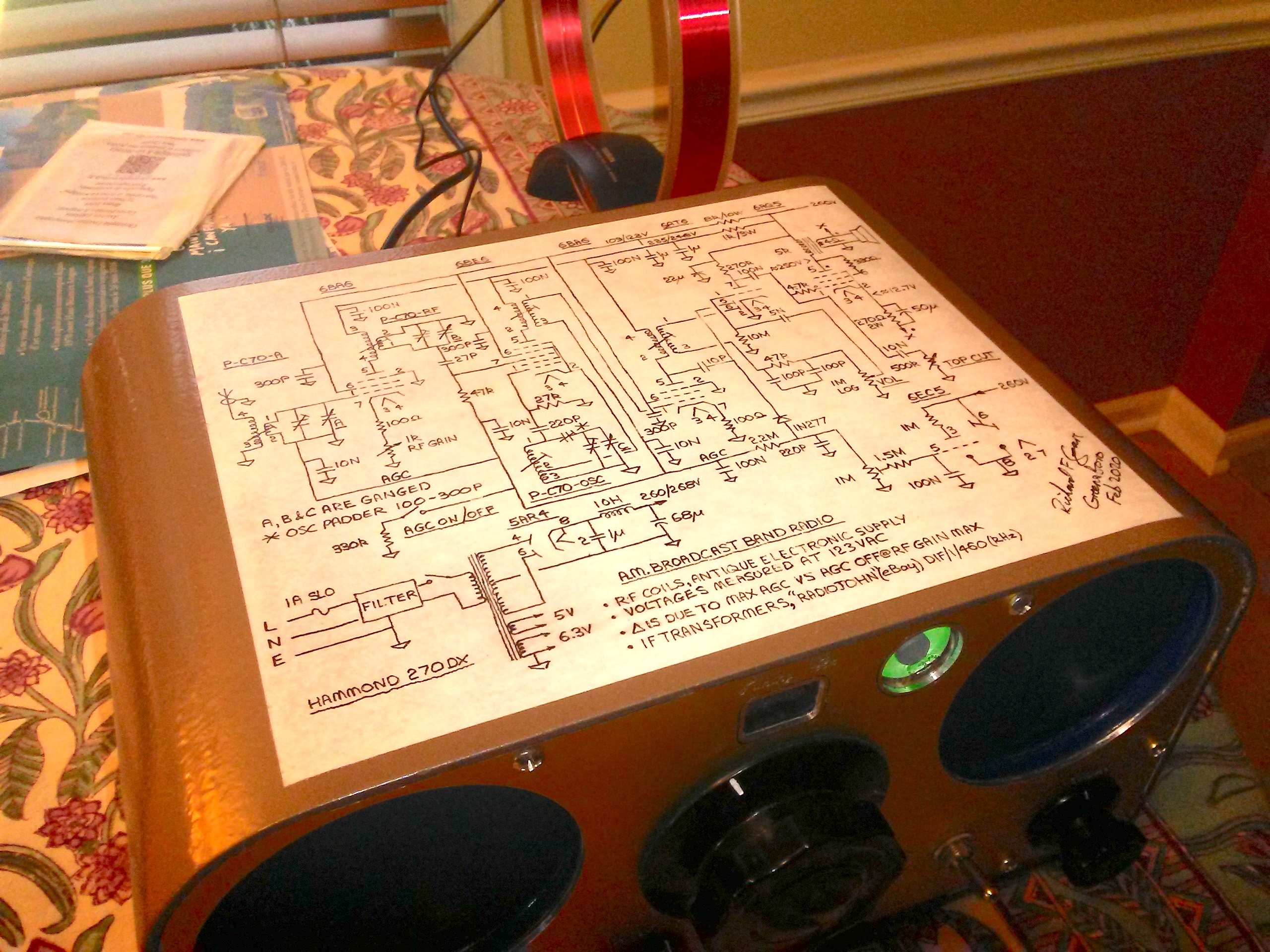
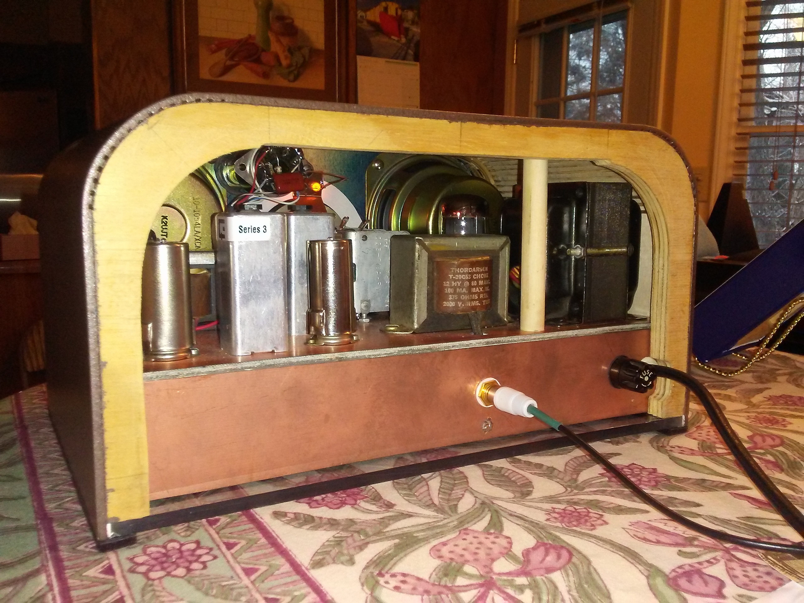
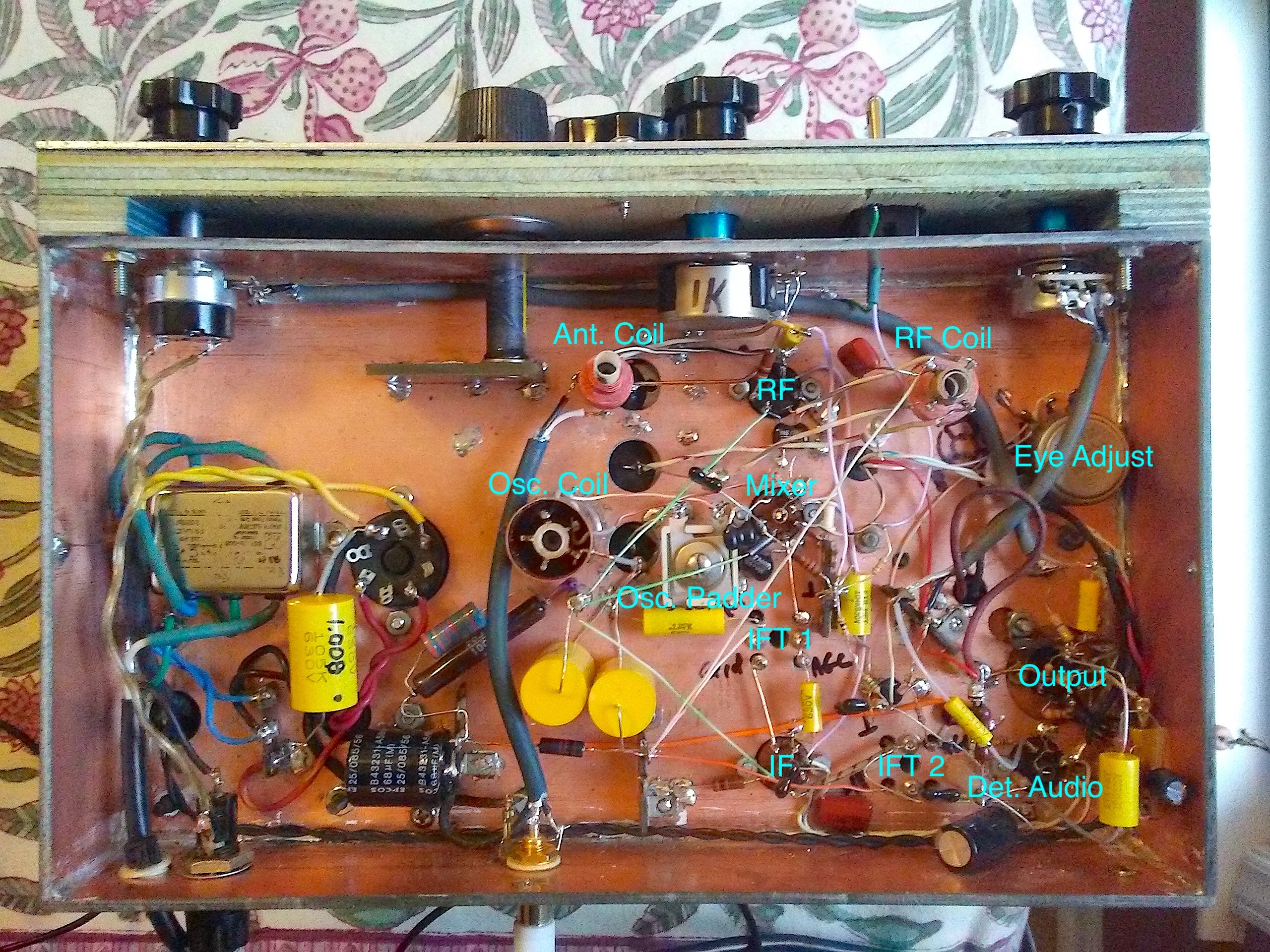
Here’s the underside again, this time as best I could, through the lexan base.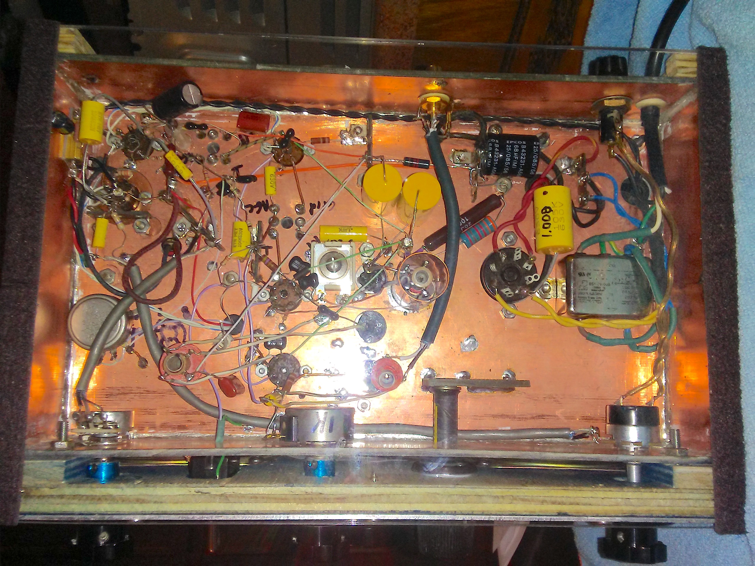
The design is inspired by the Angelfire 4 tube superhet but frankly such radios are pretty generic. An aspect of the design that differs from the “American Five” is the provision of a tuned RF stage on the front end. A stated reason for this is to improve AGC action by applying the AGC line to the RF stage also. I had intended to include an RF stage so the Angelfire design was most helpful as a reference. Another good reference is the circuit 22-3 given in the RCA Receiving Tube Manual. My interpretation includes variable gain for the RF stage by the simple expedient of placing a 1k pot in series with a 100 Ohm resistor in the cathode. It also has a “top cut” tone control, which really does help in noisy conditions. A significant modification is that I took advantage of the two diodes provided in the 6AT6 by separating the detector and AGC rectifier. This gave an improvement in audio quality. Further, I added a germanium diode to the AGC rectifier circuit, doubler fashion, to increase the AGC voltage. (I used a 1N277 simply because I had one in my sand box.) I found that even with the RF stage, the AGC action did not please me. It’s pretty much a parts bin special. Years ago, I had purchased 460kHz IF transformers from RadioJohn on eBay. In addition, I had a suitable 3 section tuning condenser, power transformer, choke and output transformer, also speakers. The antenna, RF and oscillator coils came from Antique Electronic Supply. The recommended load for a 6AQ5 in beam tetrode mode is 5k and my output transformer is 5k into 4 Ohms which fits nicely with the two 8 Ohm speakers in parallel. (I now have the 6AQ5 connected as a triode with cathode coupled negative feedback, there’s more than enough gain.) Initially, I went with a choke input power supply, otherwise the voltage would be too high. Using a 5AR4, the B+ was around 245V. Later, I added a 1µF input capacitor and changed the rectifier to a 5Y3 resulting in around 250V.
Setting it up was a challenge to me. Performing an alignment on a working radio is one thing, setting one up from scratch quite another. The deal is to get the oscillator to track the tuned frequency such that the IF frequency (460kHz) remains constant across the whole band. This is very important to maintain good sensitivity across the band. It’s no good being tuned to a frequency if the IF frequency is off. The general approach is to tune things at the low end (550kHz) using the coil slugs and at the top end (1600kHz) using the padder capacitors that are provided on the tuning condenser. I found that I could measure the local oscillator frequency with my frequency meter by just placing a probe near the oscillator coil. This is good because it minimises any loading of the oscillator which would affect the frequency. Similarly, I put a couple of turns of wire around the connection from the secondary of the RF coil to the B section of the tuning capacitor and using a scope could see precisely when the RF circuits were peaked at a given frequency. Knowing the tuned frequency, I could tune the oscillator to cause the correct IF frequency, then tune the IF transformers using a meter on the AGC line, looking for the voltage to peak (negative). Fiddling with the oscillator padder capacitor helped to get the tracking right but it took a lot of iteration. I was checking the oscillator and tuned frequencies at 100kHz intervals. I kept at it for a bit and the result was quite good. I really can’t suggest a technique to get everything in the ball park when starting out though, other than patience, observation and thought.
I should point out that since I separated the detector and AGC, the second IF transformer is only partially in the AGC act, so final IF alignment is best performed by measuring the audio signal level from a modulated test signal at the output stage. I found it better to do the RF and oscillator alignment with just a carrier.
Just for completeness:
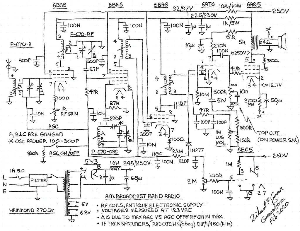
This device was intended to permit viewing two signals on a single beam oscilloscope. The input signals would have to be synchronised and though I haven’t tested this, probably of the same frequency. To cut straight to the chase, here are two signals displayed on a Knight KG-630 at 1kHz: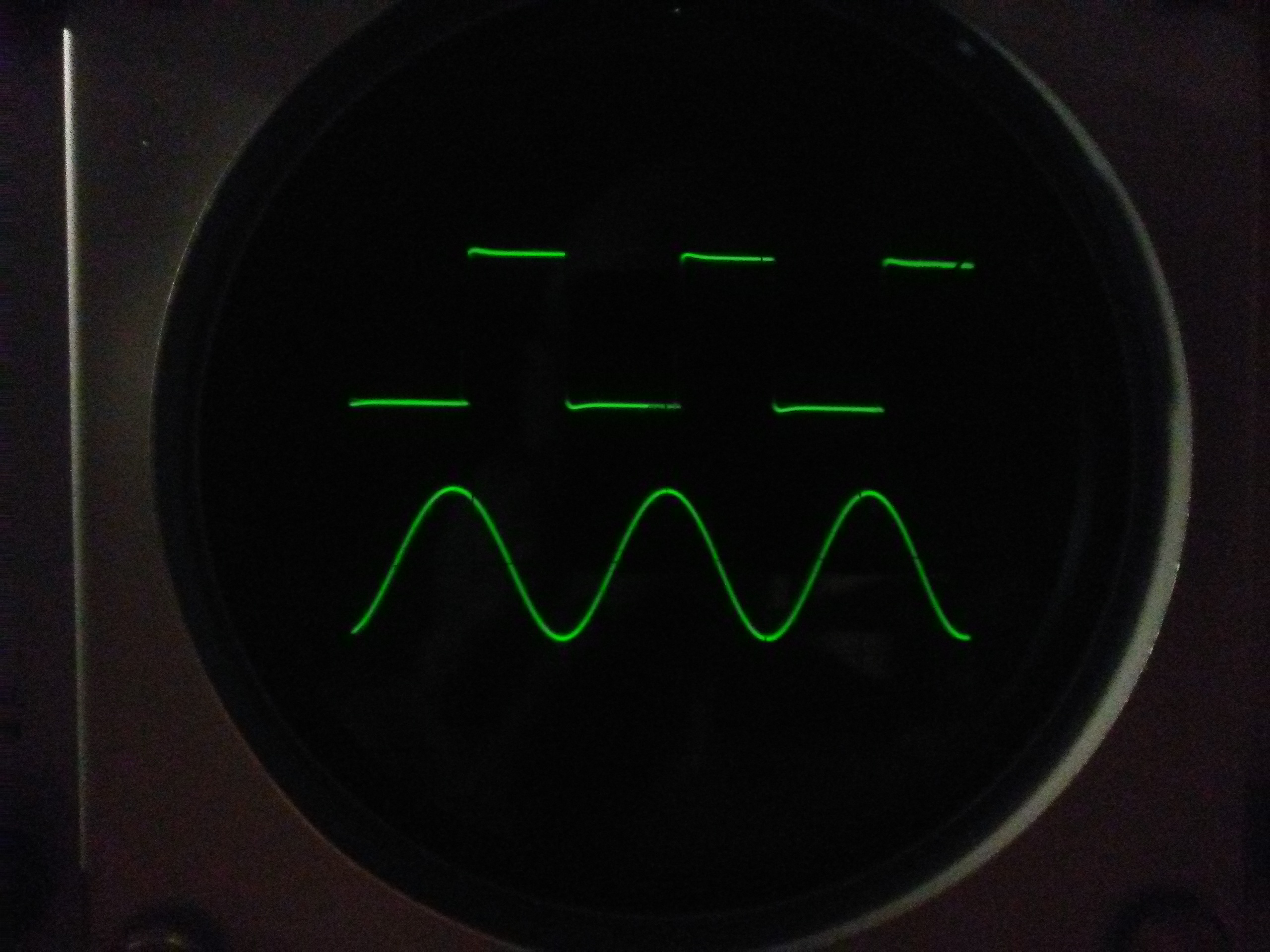
At 10kHz:
The chop rate can be selected from 200, 500, 1100 3700 Hz (as measured on my unit and rounded to the nearest 100). Here is the schematic: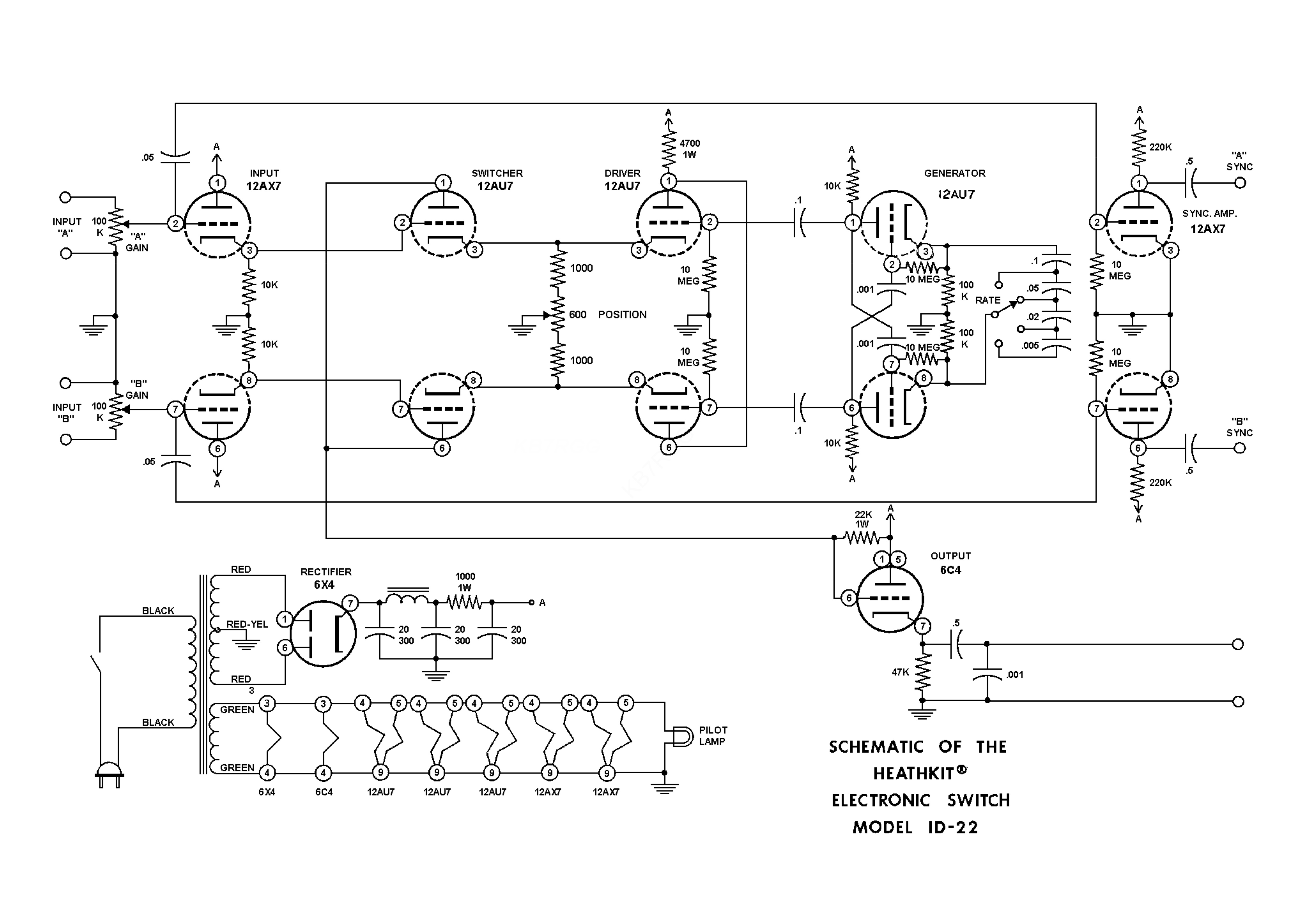
The circuit is quite straightforward. There are two input cathode followers connected to switch tubes. An astable MV generates the chop squarewave that is used to alternately bias the switch tubes off via driver cathode followers. The separation between the traces may be controlled by altering the relative “ON” DC potential of the switcher cathodes. A further cathode follower buffers the output to the oscilloscope. Cathode followers are also provided to allow a sync signal to be taken from either input, the scope must allow an external sync signal. This is so that the scope doesn’t “see” the chop waveform and try to sync to both that and the signal, resulting in a useless muddle on the screen. It is necessary to play with the chop rate along with the scope sweep frequency to get a decent display. Both the pictures above were taken with the chop at 500Hz.
As designed, the sync CFs are connected to the input grids. I found that this resulted in the input being loaded down especially as the frequency increases so I relocated the sync CF grids to the input CF cathodes. MUCH better.
Amazingly, the coupling caps in this specimen appear to be of fairly low leakage so I left them. I did add a B+ resistor to get the B+ within the electrolytic voltage specification. This is due to increasing line voltage over the years. However, the capacitor must have been marginal voltage wise, even back in the day. Other than lubing all tube pins, switches and pots, it worked. For audio application where the frequencies presented to each input will be the same, I imagine this device would have been a boon in the days when professional scopes were too expensive for most amateurs. On the other hand, I expect most people played with it, as I have!
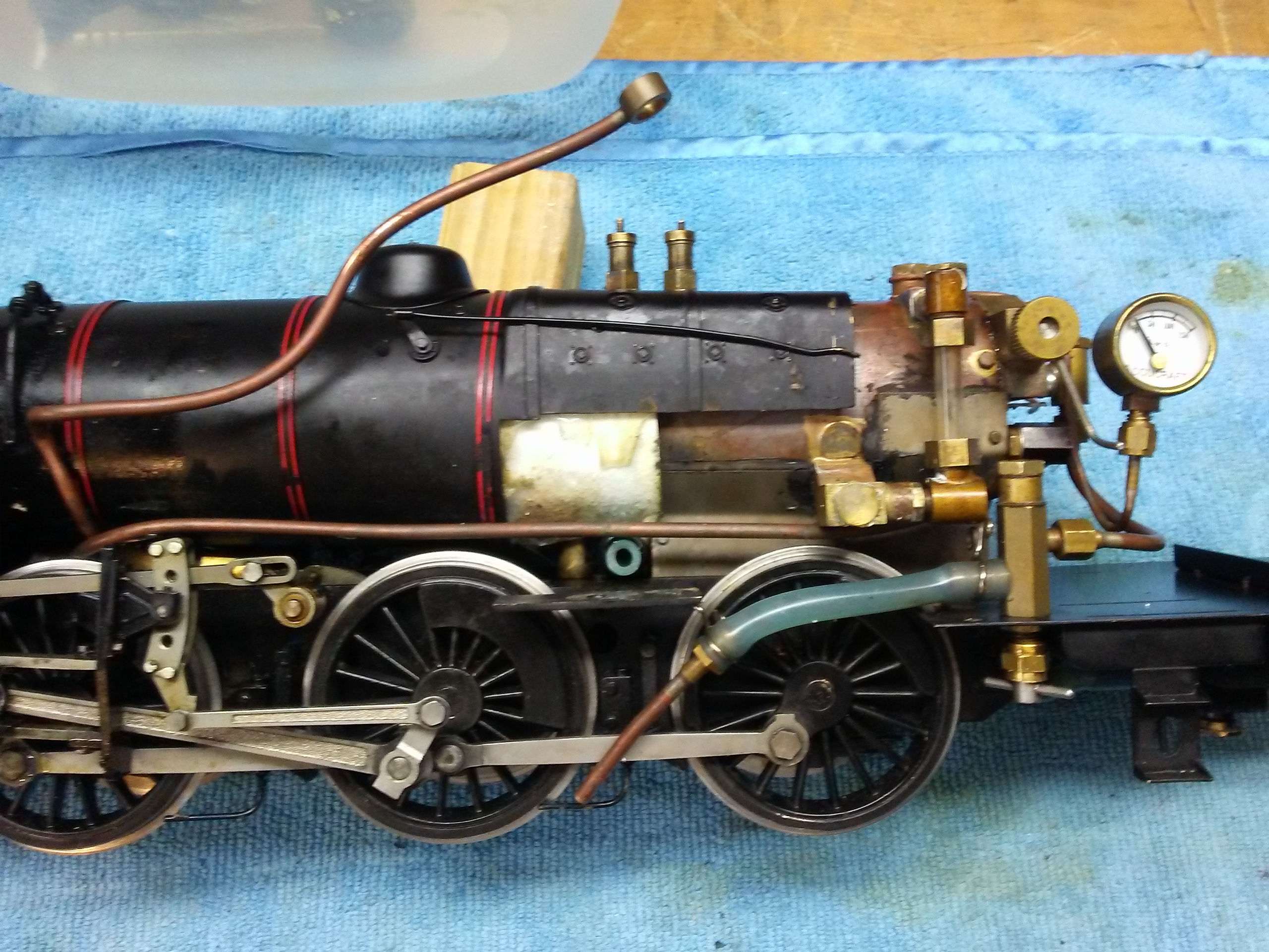
By and large the British Railways standard locomotives, designed under RA Riddles, were successful machines, capable for the work they were intended to perform, reasonably efficient, reliable and easy to maintain. They were also handsome, and I think that the BR 4MT Tank loco is one of the most handsome tank locos of them all. The 4 is the power (the classification for steam is strictly not power but tractive effort and runs from lowest to highest being 9 as in 9F) classification while the MT stands for mixed traffic, i.e. freight as well as passenger trains. I remember as a little boy being taken to meet the crew of one of them at Waterloo station and was strongly impressed. This loco is contemporary with the Rebuilt Merchant Navy Pacific (35028) that I have. I duly located and bought one to partner with said Pacific. Two versions of this model have been released, first by the Gauge 1 Model Company and later by Bowande (Wuhu). The G1 MoCo is now defunct and their designs have to some extent passed on to Accucraft. Both model runs sold out quickly, it is a popular loco! I finally located an elderly one that turned out to need to urgent attention (more below). Given the extent of necessary repairs it needed, I paid too much for it, c’est la vie. The previous owner must have realised what a mess it was in but didn’t come clean with the selling agent I think.
The G1 MoCo model is spirit fired, and is equipped with a draft blower that was completely blocked in my example. It has two cylinders with faux outside Walschearts valve gear (nicely done) and inside valves with slip eccentrics for reversing. It also has an axle and a hand water pump, as is usual with spirit fired gauge 1 loco. (The Bowande version is fired by gas and has no blower or water pump.)
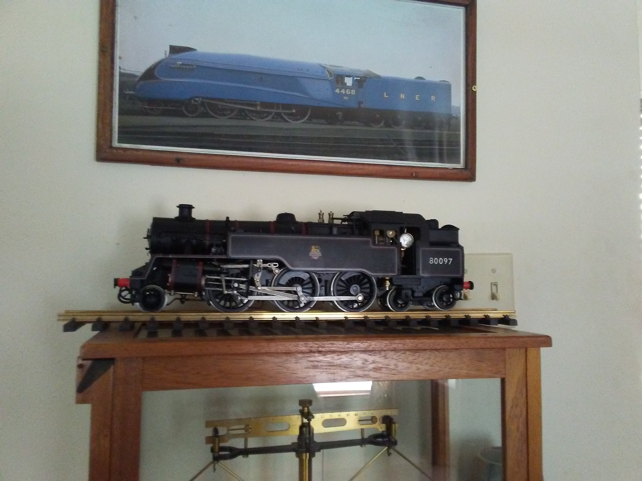
A handsome machine, the A4 too! Maybe the scales below will weigh the relative merits of the designs.
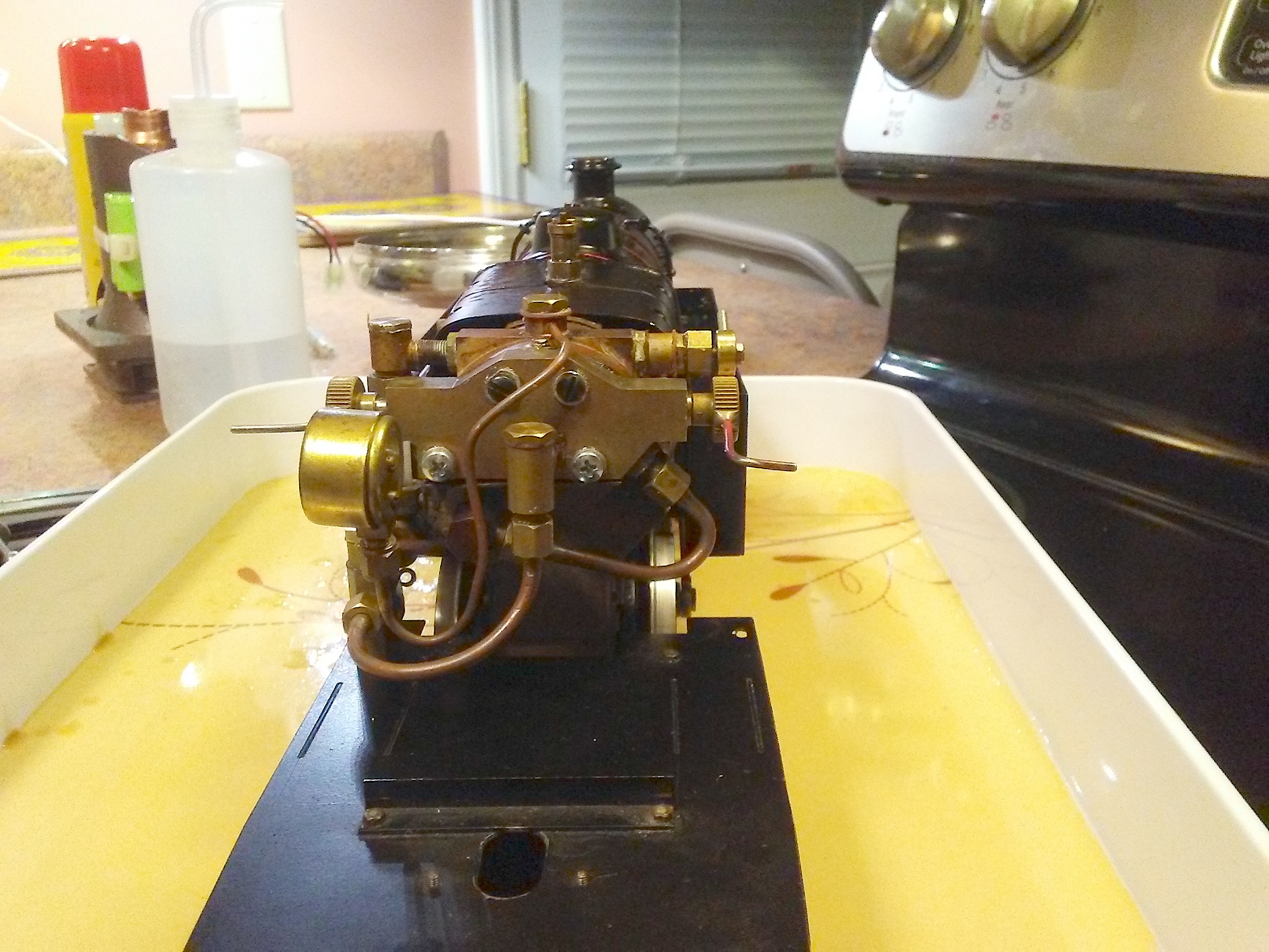
To the troubles: The blower was blocked and this led me to wash out the boiler. Quite a bit of sediment both oily and solid, came out. I washed it out with distilled vinegar three times but was unable to clear the blower line. So, the manifold had to come off. It is held to the backhead by 4 M3x0.5 screws, the upper two screw into blind holes while the lower two are open into the boiler. Well, the top screws came out fine. But, the lower screw heads simply fell off when I applied a screwdriver. I didn’t panic. (Not bad for me.) I pried the manifold off using a wrench on each of the protruding square shaped lugs on each side of the manifold so no danger of scratching the faying surfaces. (The lugs house the blower and regulator valves.) Having done that, I started poking about in the two lower screw holes and thank goodness, the screws had corroded completely away so all I had to do was run a tapping drill and tap through each. With galvanic corrosion between steel and brass or copper, the steel looses. (In fact, it is possible to remove a broken tap in brass or copper by dissolving it using an alum solution and heat. I initially thought I might have to do that.)
I cleaned everything up including the blower line and then re-attached the manifold just using silicone grease (Dow Corning) as the joint compound. I took care to make sure that the threaded holes were well packed with grease. I use this on all the pressure fitting threads too. There is no need to use fibre washers under them. For what’s it’s worth (probably not much) I will replace the screws with stainless steel items when they arrive.
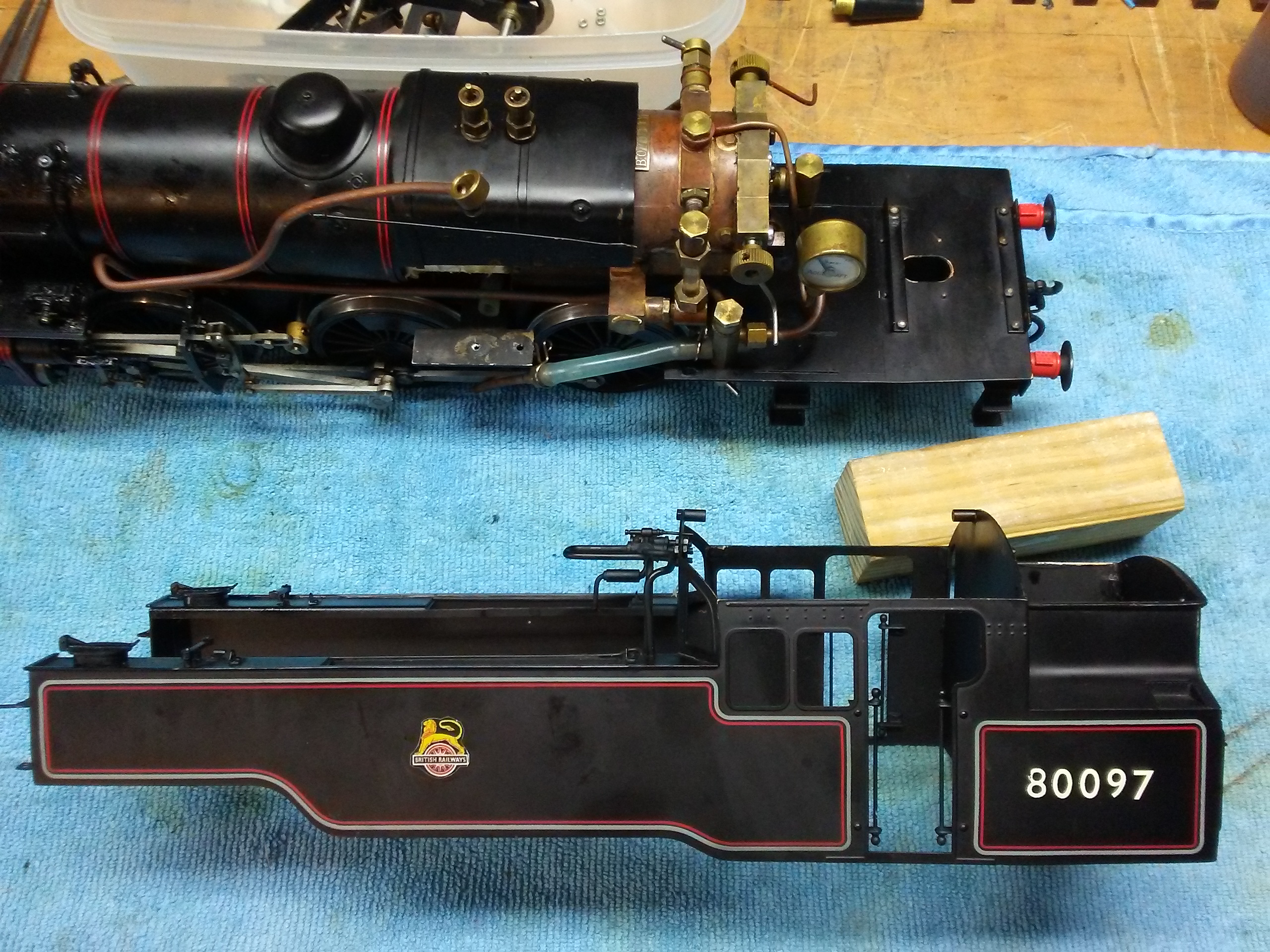
Here’s the cab and side tank covers. I was glad to discover that this assembly is easy to remove, just two screws in the back (just above the buffer beam), two screws into the cab floor from underneath and two screws in tabs at the front of each tank.
I wound up removing the side tanks also. The tank containing the hand pump had been gooped up with RTV and the transfer tube between the tanks was blocked! There was no need for the RTV, the tank doesn’t leak! The joint between the pump base and the tank was the likely culprit. Again, I sealed the surfaces using silicone grease.
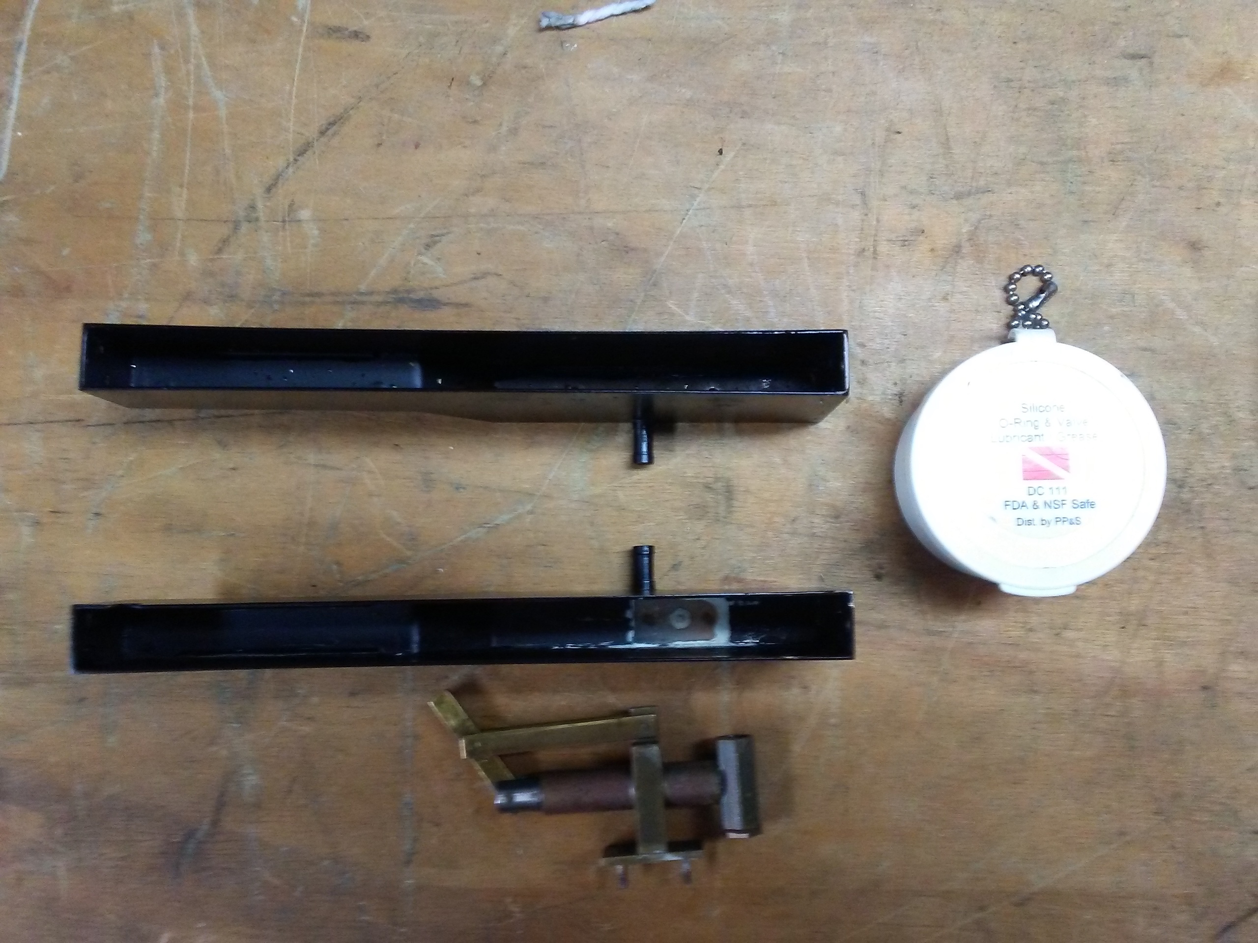
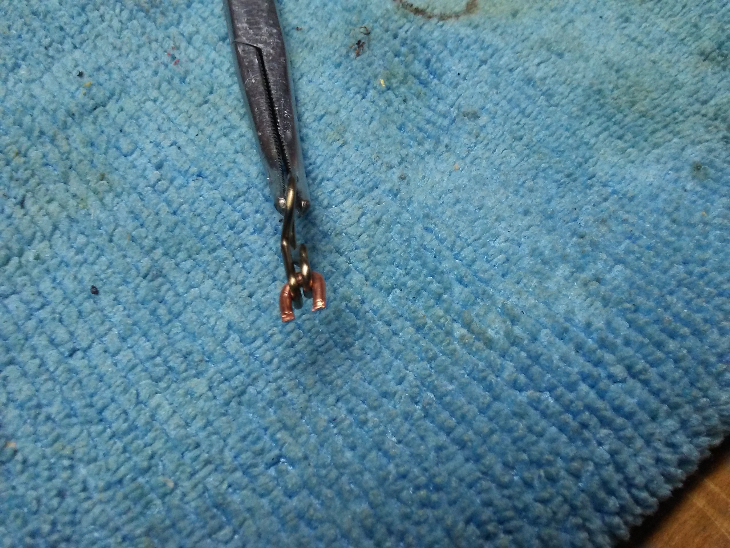
This view shows one end of the water balance tube for the two tanks.
The tube has fiddly sprung clips on each end and I have nothing suitable to grip them with so I put a 16 SWG copper wire retainer through the ends and simply snipped it away when the clips were in place.
Running the loco:
Well, I now have fierce blower action.
I repacked the burner tubes with 22 strands of ceramic string, leaving about 3/8″ exposed.
Having filled the lubricator and the boiler, I fitted the fan, opened the spirit tap and lit her up. Pressure rose nicely. I opened the drain cocks and the lubricator valve slightly (too much and the loco will run without opening the regulator). Once around 20lb was showing, I opened the blower and removed the fan. Pressure climbed quickly to an indicated 50PSI. Opening the regulator a little and pushing, plenty of oily water was ejected from the drain cocks. Once that was done, I closed the cocks, opened the regulator again and away she went! She runs with little temperament. The only thing is that the axle pump only just keeps up and that was with no load. Still, with occasional top ups of the tanks she run beautifully for quite some time and kept running until the gauge had fallen to well under half pressure (this includes about 50′ of 1% gradient each lap). The loco clicks as she runs and I have noticed this clicking when watching this design run on YouTube. The axle pump is driven via a bell crank, there are five pin joints between the eccentric and the pump plunger resulting in considerable lost motion, I suspect that with the obvious wear this loco has, the extra lost motion is responsible for the clicking. I also expect lost motion may be responsible for the weak pumping action too. That’s a project for another day because the pump is buried under (or over) the inside valve gear.
Oh, no sign of leaks anywhere! The silicone grease works well.
11/26/17: My friend Barry Coward visited from England and made this excellent narrated (by your truly) video of this loco running.
9/9/17: I’ve just had a very fine run with 232U1. I have equipped her with radio control, on the regulator only. This makes running on my graded track much less fraught! The RC transmitter and receiver come from Peter Spoerer in England. The transmitter is a neat device that is purpose built for train control and fits neatly in the palm of one hand. I don’t like the usual big units that look like video game controllers.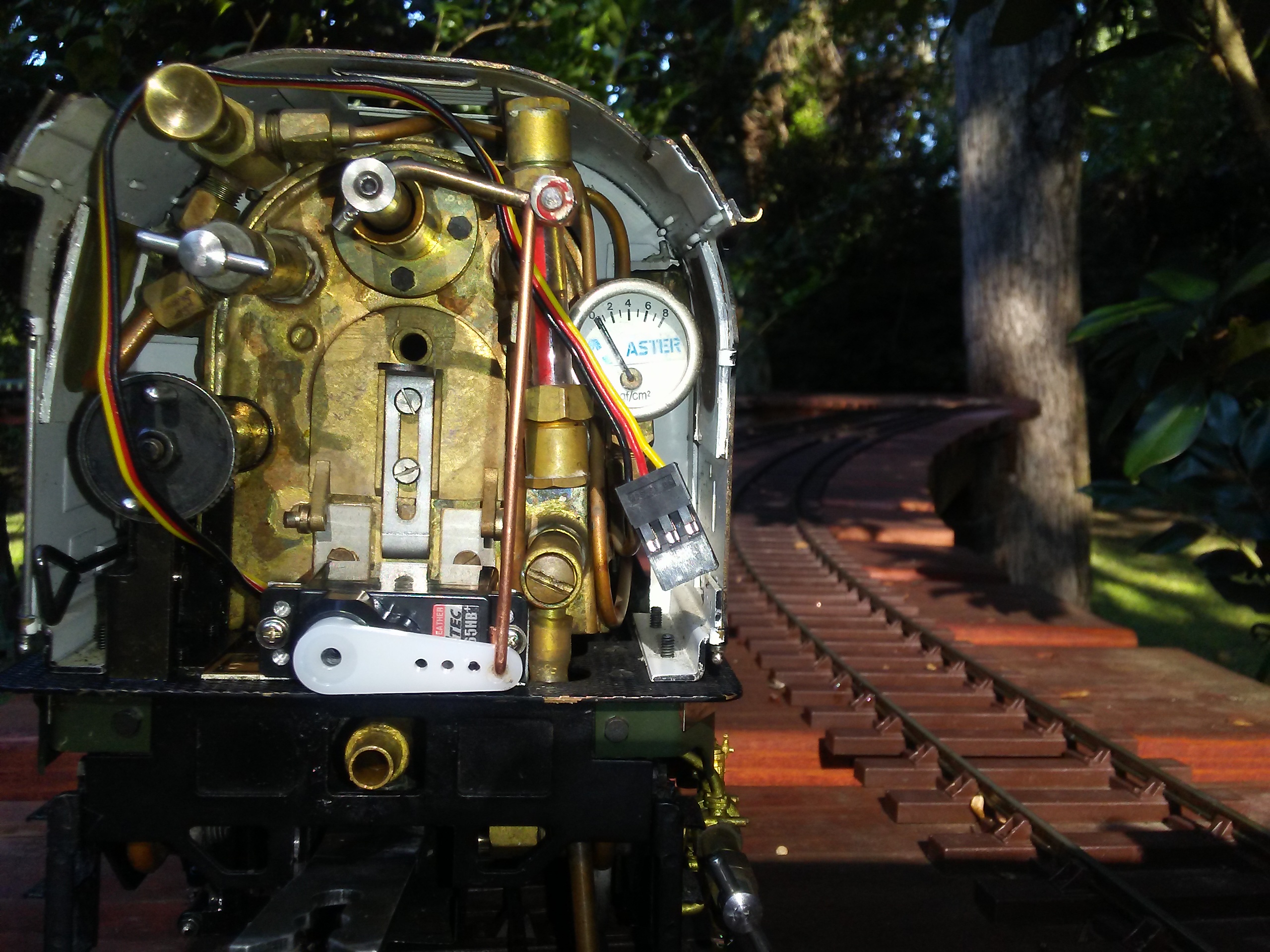
The RC installation is completely reversible, the servo bracket is clamped under two existing screws on the footplate. I tucked the battery pack in the gap between the fuel tank and the tender and the receiver simply lies on top of the tender inside the coal rave. I will make a shield to go over the servo for when I attempt coal firing. RC is not necessary on the blower (fortunately because there isn’t much room if I want to coal fire with RC fitted) because with the very soft blast of a compound, (I have found) it is necessary to run with the blower slightly open so there isn’t a concern about the flame popping back when she comes to a halt. The water usage is notably lower than that of the Merchant Navy however, fuel economy is comparable. I run both locos in full gear because it is easier and the reversers are too hot and fiddly to adjust once steam has been raised*. The fuel economy of 232U1 was terrible. I discovered that a previous owner had raised the burner screen about 3mm and cut higher wicks. I returned it to the original state and the economy improved a lot. What was happening was that the fuel was evaporating too fast for the available air supply so I had a fuel rich and thus relatively cool flame. I also put some silicone grease around the smokebox door, this resulted in the loco maintaining pressure with a much smaller blower opening, though the corrected burner will be helping this too. She does suffer the compound starting problem, not on the level or from cold, but on the gradient. The Merchant Navy has no problem restarting this train on the grade but 232U1 will not. This is because only the two smaller cylinders are available at starting. However, once she is moving and compounding (using all four cylinders) the pull is STRONG. I reckon she could pull perhaps double the weight up the grade.
* Also the run time with each, something over 30 minutes is quite enough for me. It’s time for tea after that!
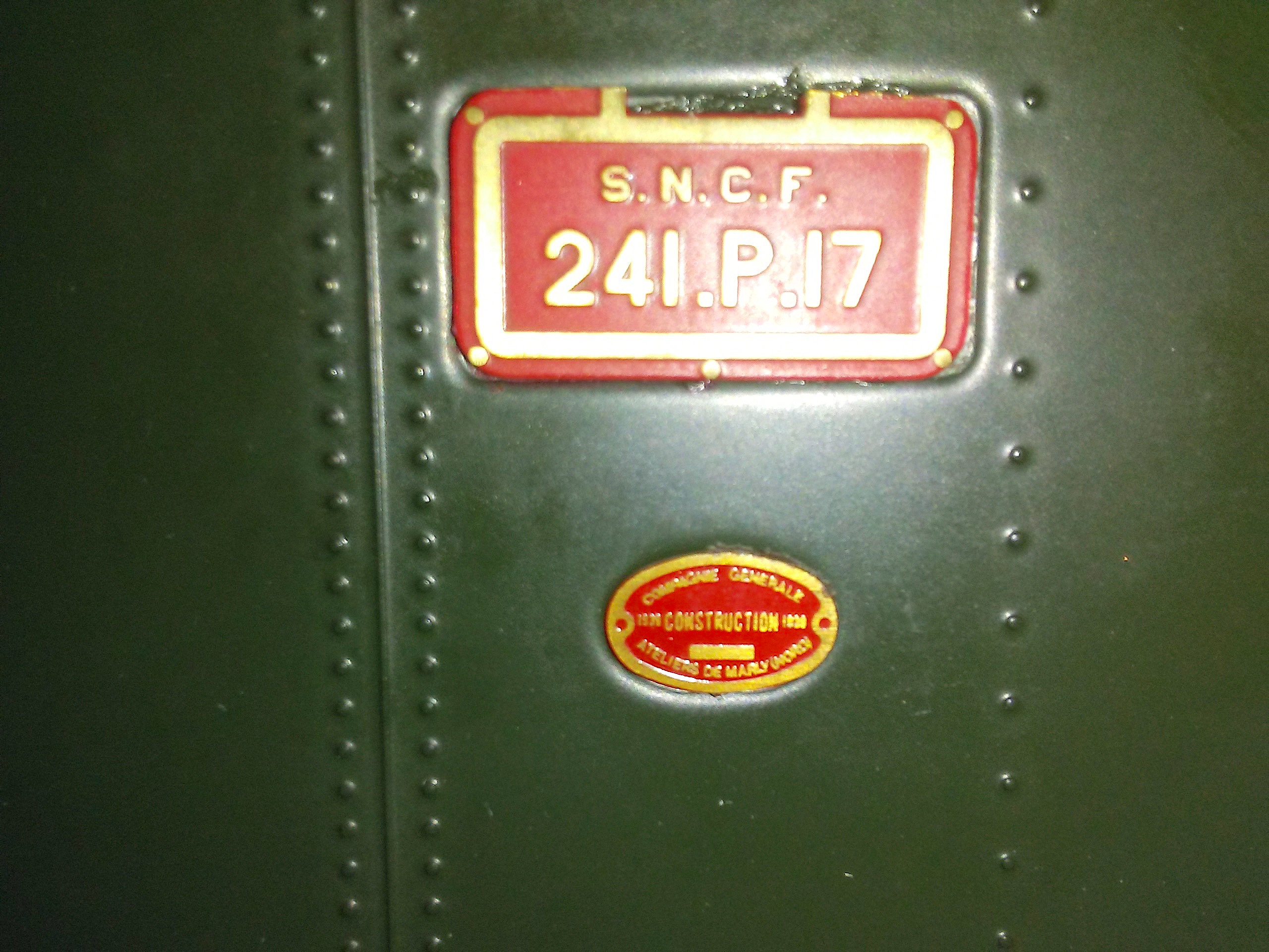
8/20/17: The European 4-6-4 (or 232 using French nomenclature) is known as a Baltic, and sometimes incorrectly as a Hudson. However, the 4-6-4 wheel arrangement first appeared in 1911 as du Bousquet’s last design, a 4 cylinder compound, and came to be known as a Baltic because the Nord Express served the Baltic coast. The 4-6-4 was introduced in America by New York Central in 1927, to haul crack passenger trains along the Hudson River valley and became known as Hudsons and fine they were too. Having digressed a little, back to the French story. SNCF 232U1 was the last of a batch of 8 Baltic locomotives commissioned just before WW2. Marc de Caso was the designer and the opportunity was taken once again to compare compound expansion with simple. 4 of the batch were built as 3 cylinder simples, 3 as 4 cylinder compounds having Dabeg rotary cam poppet valve gear. Whilst these compounds showed about a 12% savings on coal over the simples, the valve gear was not satisfactory. The last of the batch was not built until after the war and de Caso’s proposal to build the final one as a 4 cylinder compound having exceptionally long travel Walschaert’s gear with piston valves was accepted. (In full gear, the travel of the HP valves was 9.2″ and that of the LP valves, 11.7″, resulting in large valve openings at short cutoff settings.) The locomotive was successful, showing a further increase in coal economy of around 12% over the poppet valve compounds and able to sustain 3300HP at the drawbar. She was efficient and apparently easy to drive, also having a mechanical stoker. Our British locos were too small for such to be of any real benefit, supposedly. Diesel and electric was coming and so 232U1 remained unique, nevertheless she racked up over a million km in 12 years, with no problems. She is preserved at the transport museum in Mulhouse and is perhaps the best indication of what steam technology could accomplish. I say best because while the French had other successful compounds, notably the Chapelon 242A1 that was also unique and somewhat more powerful, this one was perhaps the most rounded design, ready for a future that didn’t come. de Caso knew that 232U1 was the swan song for French steam locomotion and supposedly the streak along each side represented a swan and she became know as la Divine.
For some reason, British engineers never really made compound expansion work in the sense of coal economy. There were a couple of notable failed attempts, failed because the engineers involved tried to take too many steps at once. The French tend to be academically brilliant and able to translate theoretical predictions into measurable results. After all, the application of thermodynamics to heat engine cycle analysis originated with Msr Carnot and the French steam engineers took it seriously.
Moving on to the Aster Gauge 1 model. To me, the successful design of a proper compound expansion model in gauge 1 is an extraordinary accomplishment. Given the attitude of British engineers to compound expansion, it is ironic that the designer who made such models possible was a British citizen (J.T. van Riemsdijk). He was Mechanical Engineering curator of the science museum when I was little. I remember the apparently endless glass cases containing working loco models, each operable on compressed air by pressing a button (paradise for a little boy), many of which were 1 gauge! Aster produced 4 compound models based on his work of which this specimen is 232U1 serial number 1! It is further notable in having a wet firebox capable of burning coal as well as spirit. The model comes with a grate and ash pan as well as a spirit burner. The spirit tank in the tender may be replaced with a coal bunker. Most fire tube models at this scale have a dry firebox and burn spirit only, as is the case with the superb Aster rebuilt Merchant Navy, that I described in an earlier post. A 1 Gauge luminary told me that the Rebuilt Merchant Navy is a museum quality model. I beg to demur, yes it is superb and an excellent performer, but museum quality it is not. The 232U1 on the other hand most certainly is of museum quality.
I wonder what’s in this case?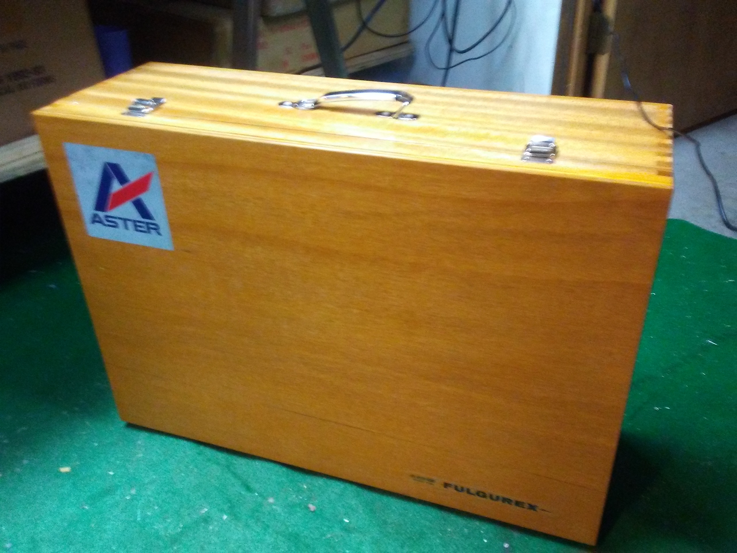
Aha! A warning, this is NOT a toy!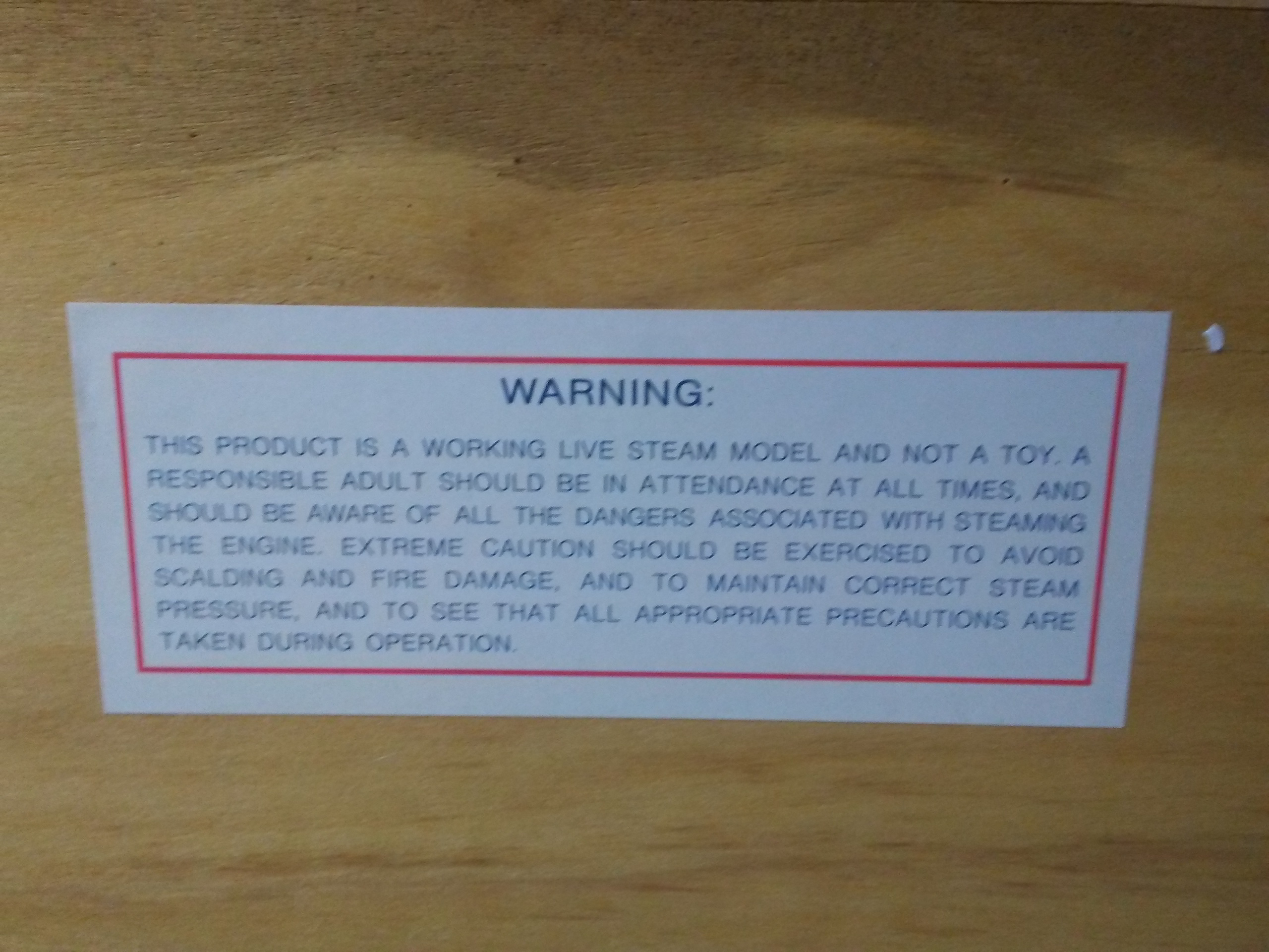
Inner lid: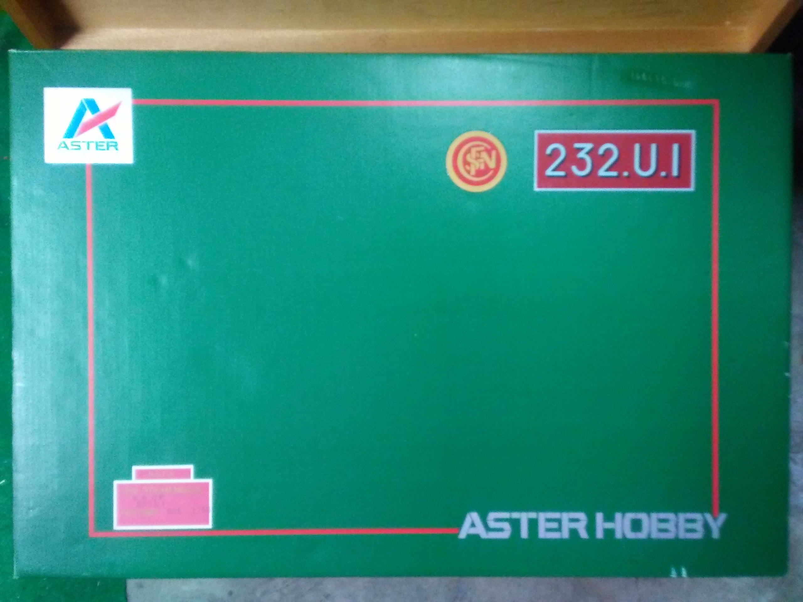
Under the lid, assembly and operation manual and book of exploded assembly drawings: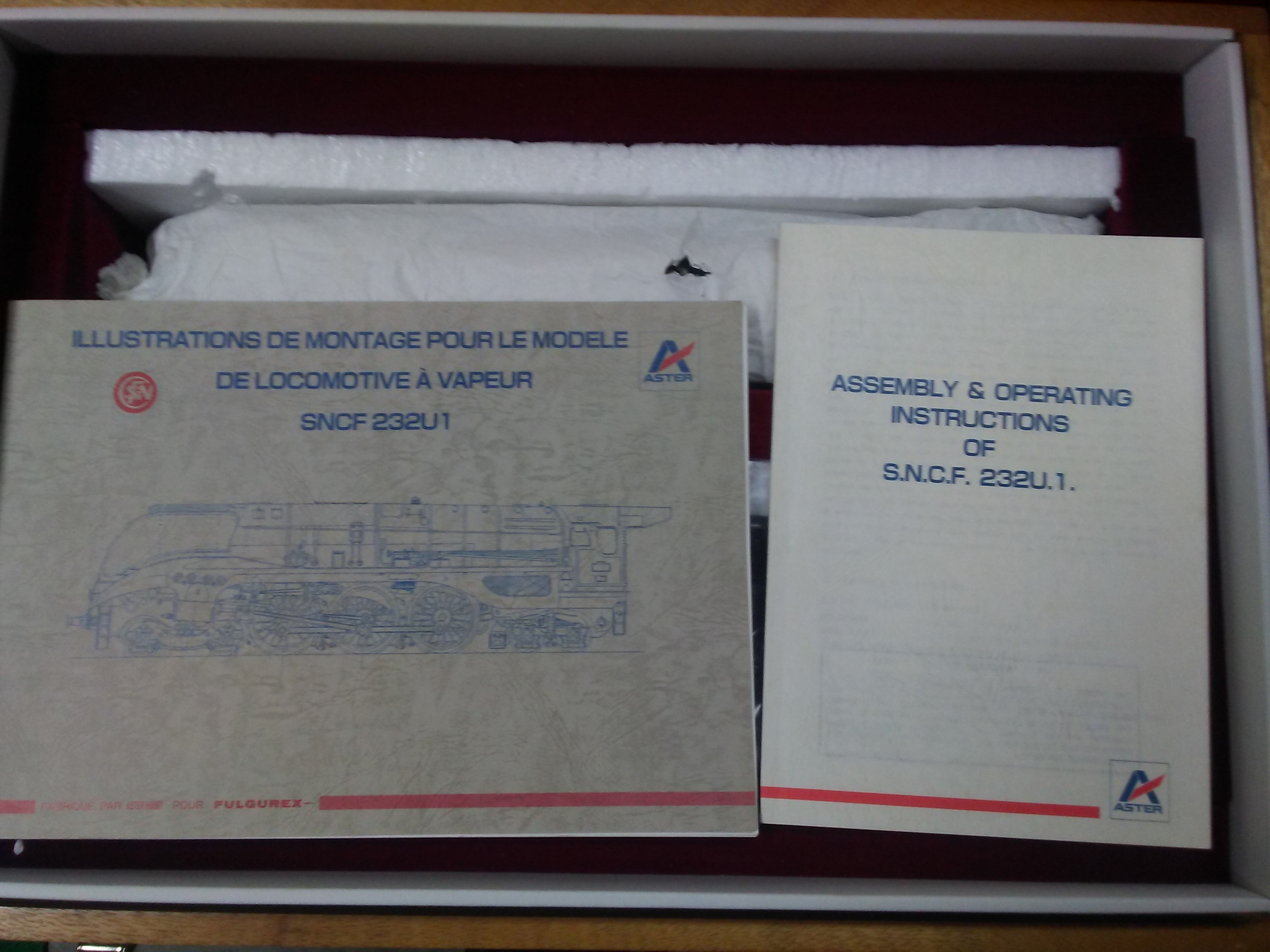
Now to the loco and tender, still in the original (and slightly oily) tissue. The tool laying on top is the flue brush.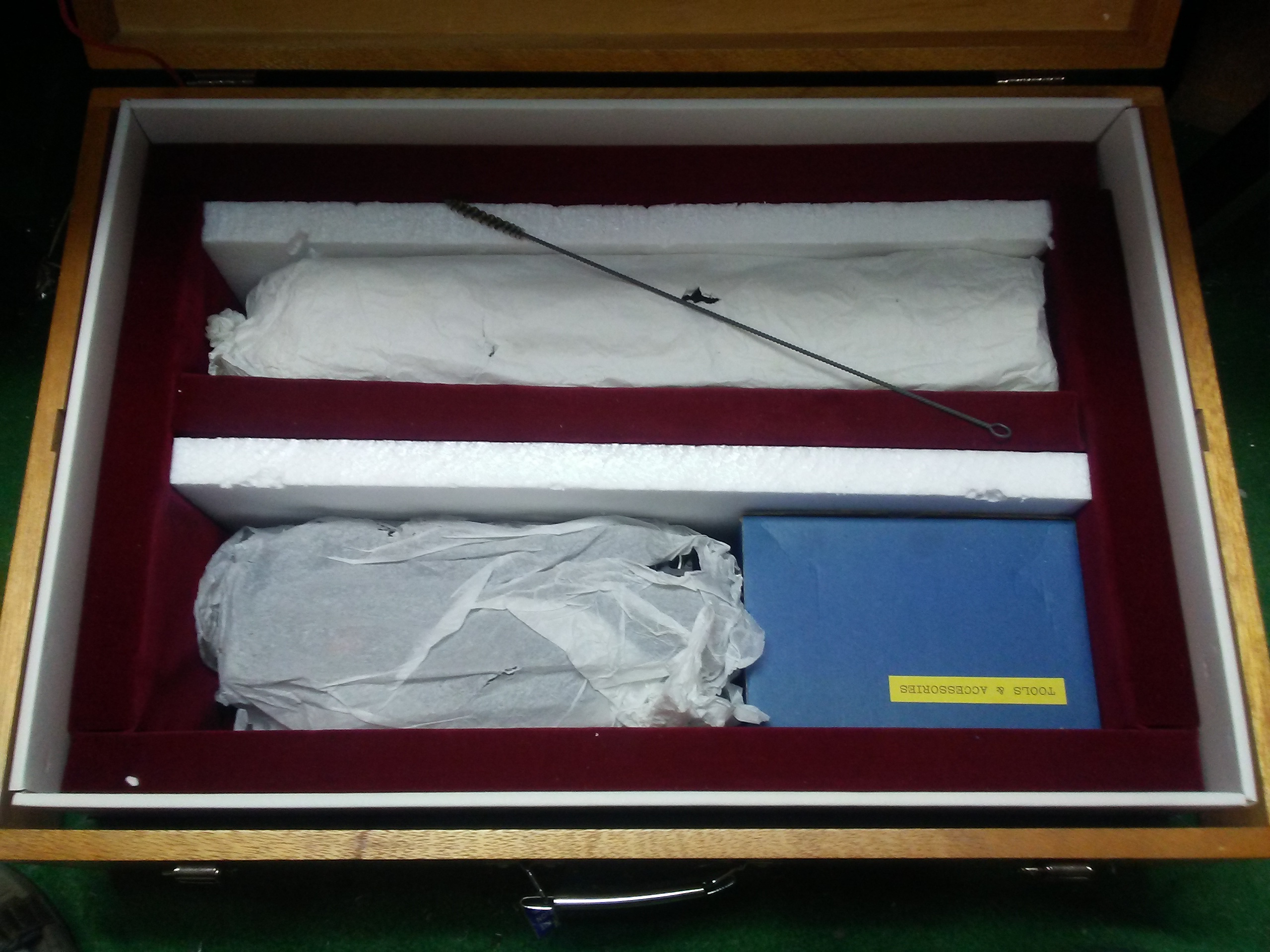
Tender first!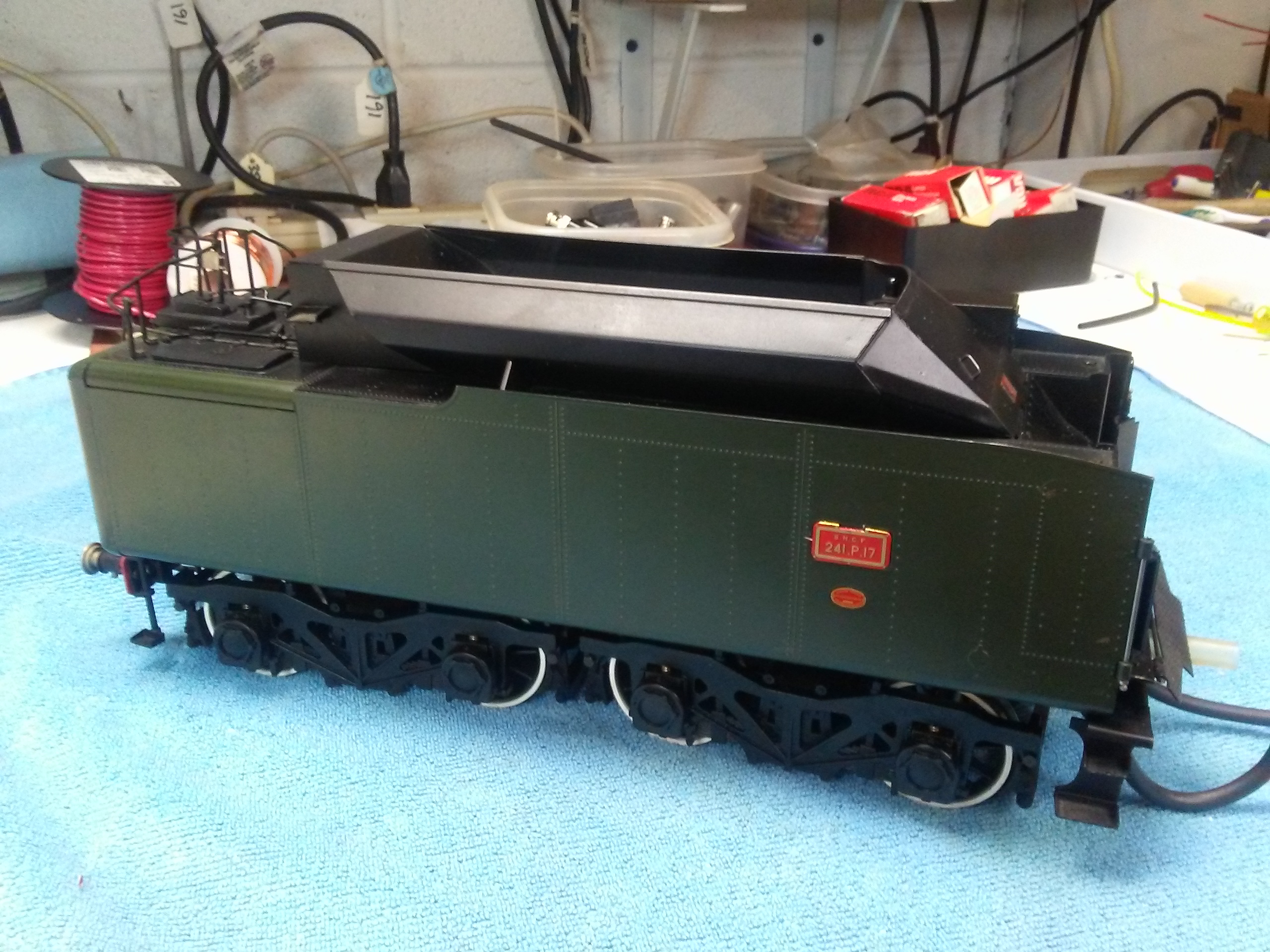
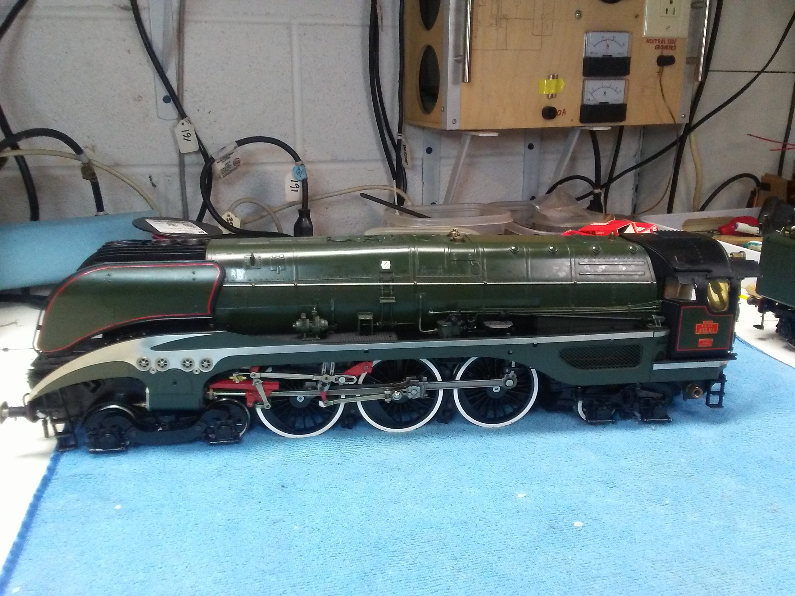
The loco has outside Walschaerts valve gear. Rocking levers transmit the motion to the valve for each inside cylinder. The original did have inside combination levers though.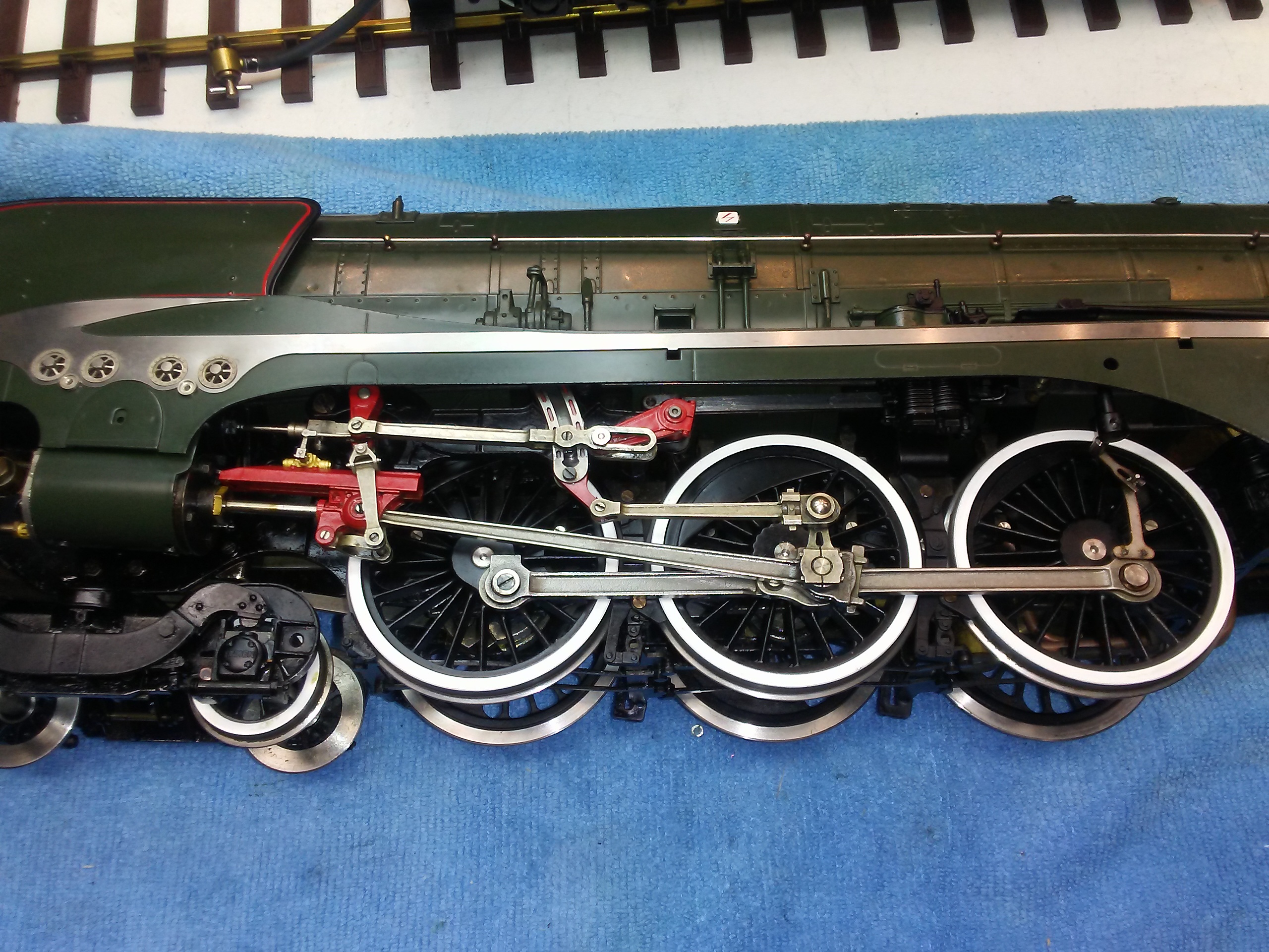
Four cylinders, inside high pressure, outside low pressure. These are cast bronze, I think.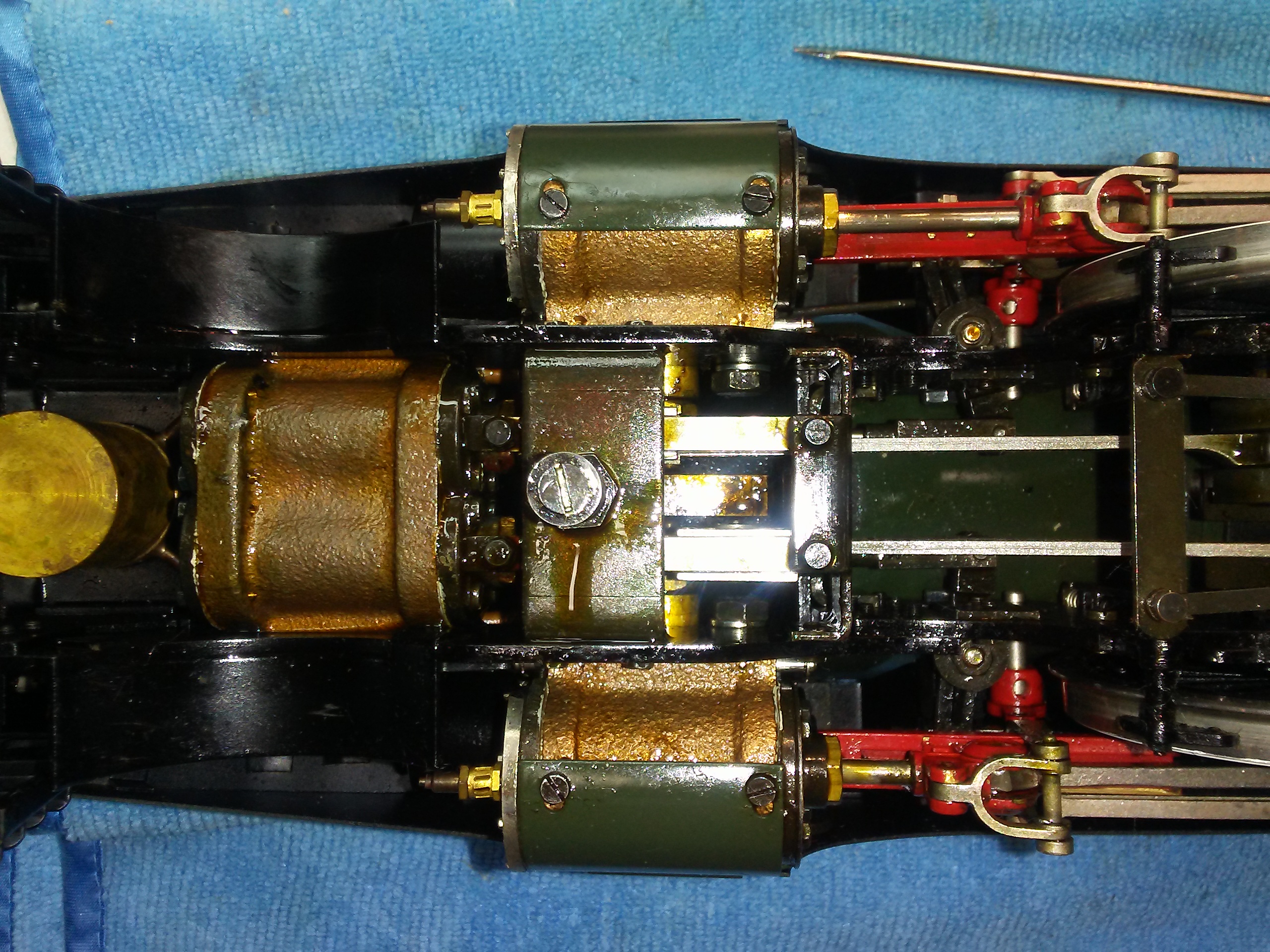
Leading crank axle for inside cylinders. 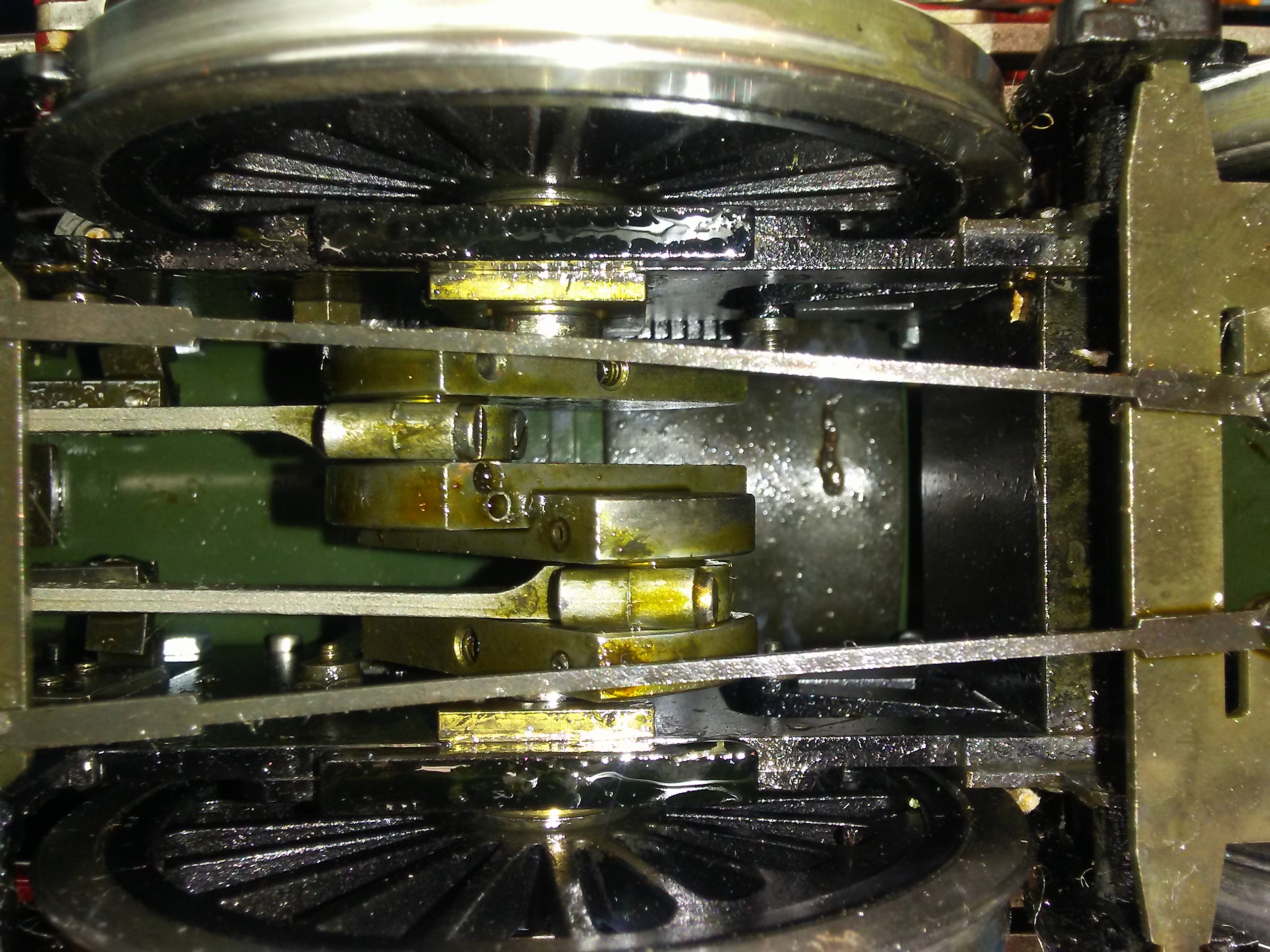
The eccentric on the middle axle drives the boiler feed pump. What I can’t show is that the suspension has equalization beams, another technique that was eschewed by British Engineers. I can’t help think that if the Bullied Pacifics has been so equipped, they would have an entirely different reputation! I have described the equalisation of the front truck further down.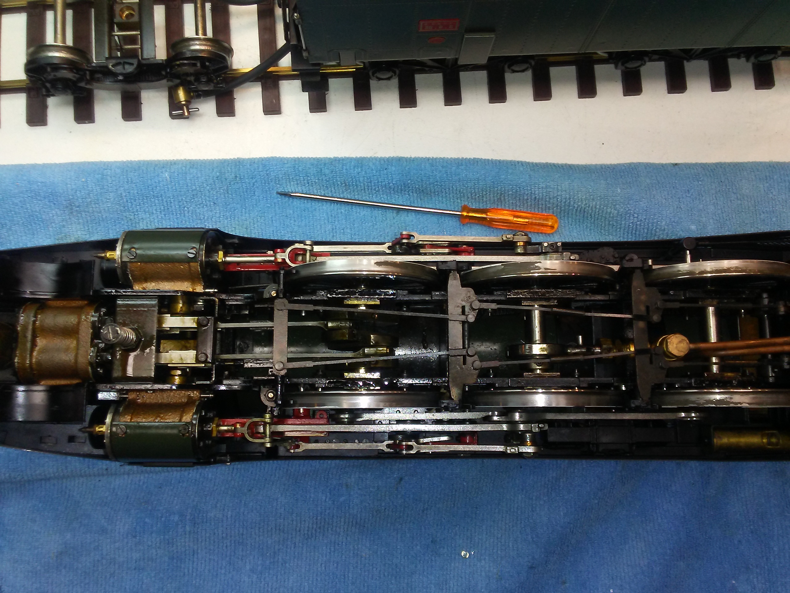
At the front is the Roscoe displacement lubricator. The leading truck not only has compensated suspension but the proper swing link system to guide the loco smoothly into turns. As the truck moves off centre, it causes the front of the loco to lift a little, the lifting force causes a turning moment that will cause the front of the loco to move in the direction of the curve, smoothly following the truck (or bogie).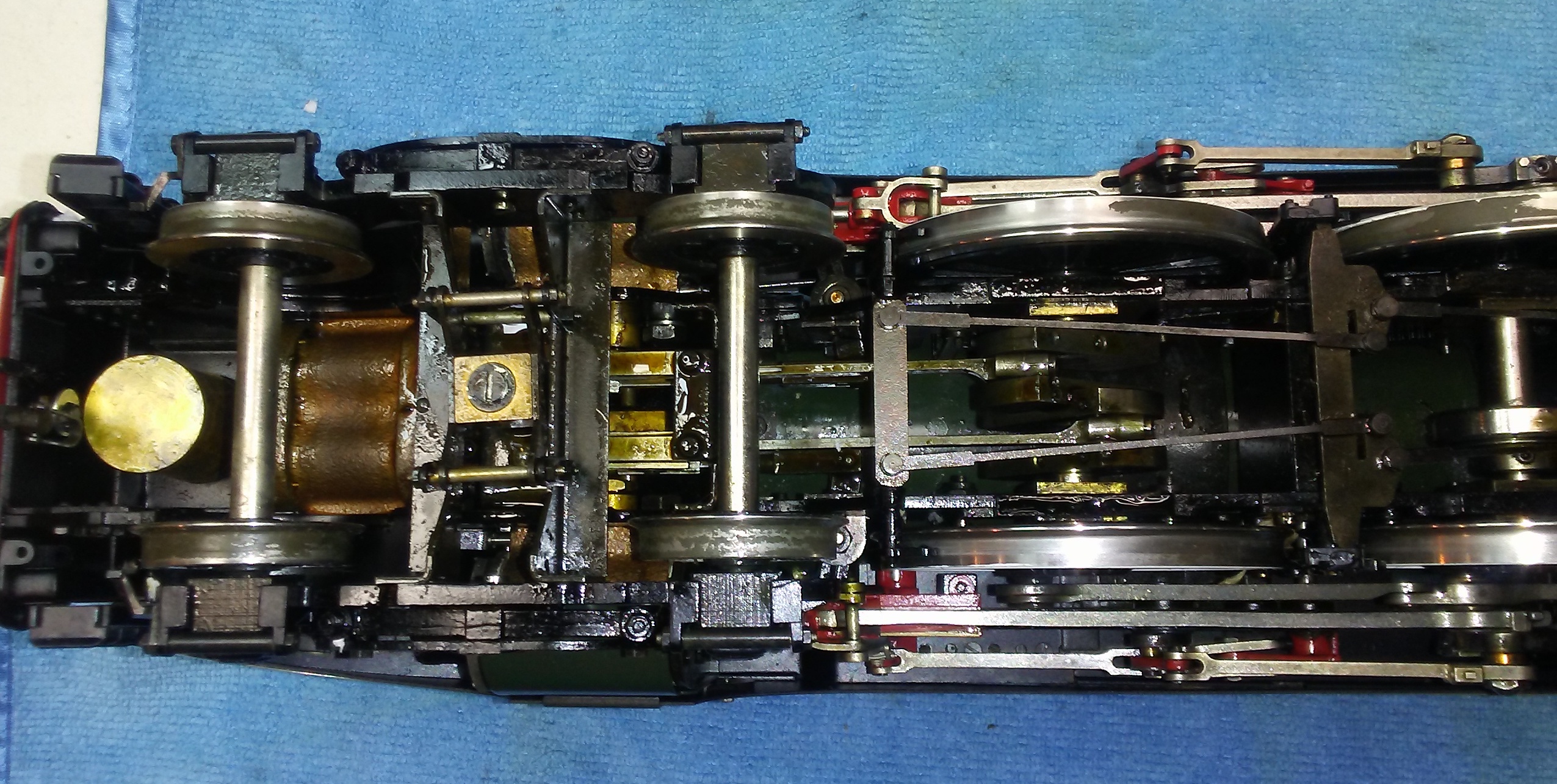
Here’s the swing links either side of the pivot bearing. Each axle box is sprung. The force from each pair of boxes is coupled to the truck by a beam that is pivoted at the centre, thereby providing load equalization.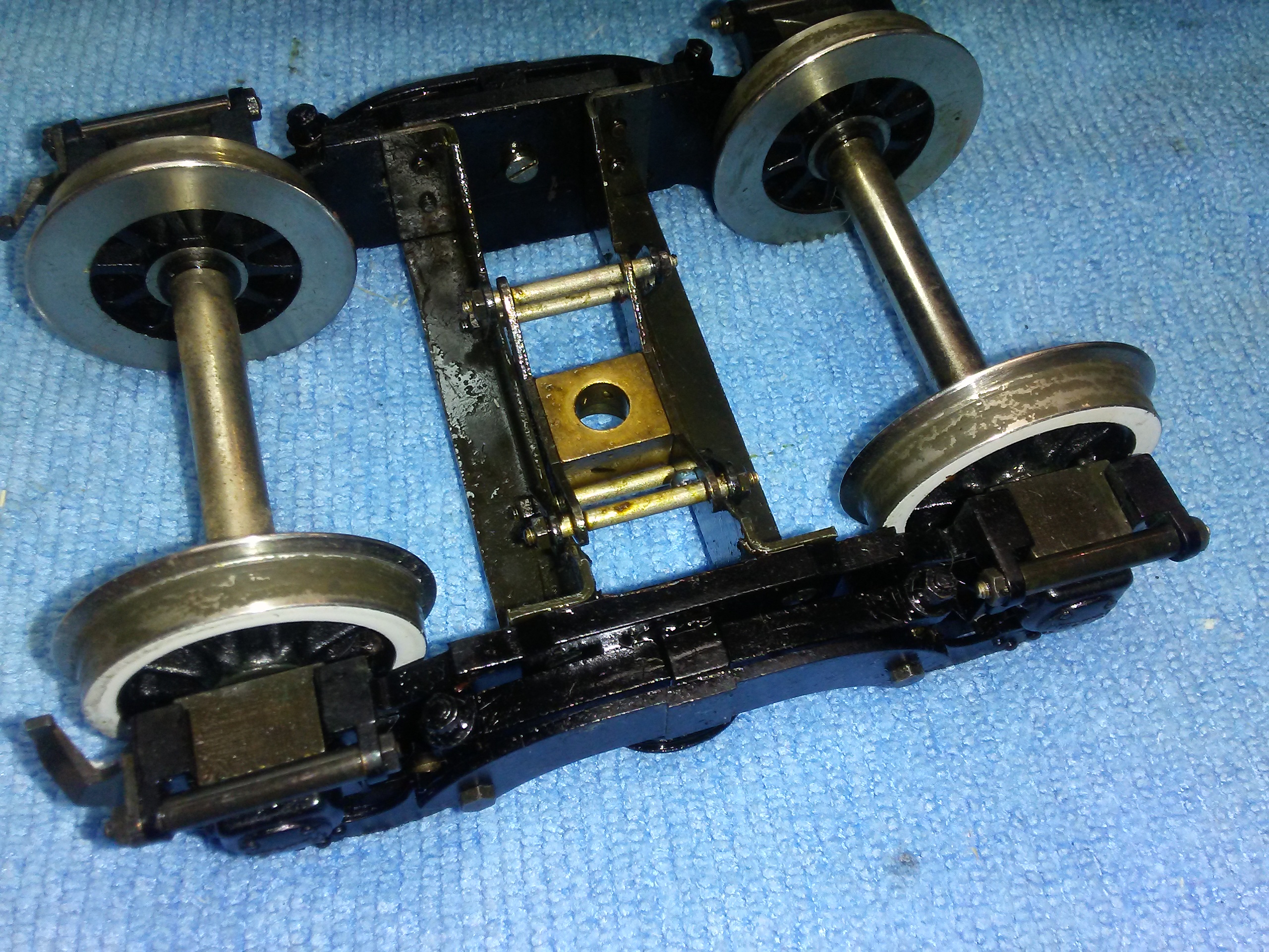
Here’s the rear truck with the spirit burner affixed, also showing drag/control links.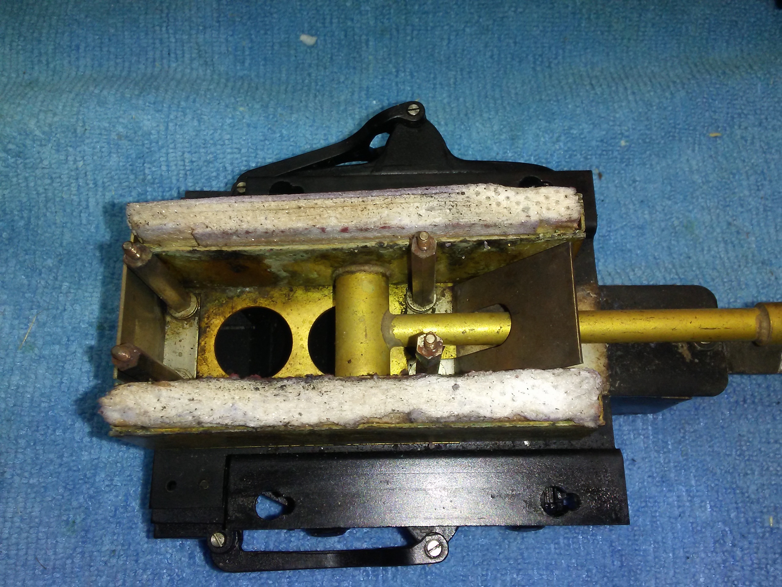
There is a link each side that connects the truck to the loco such that as the truck moves from side to side, it also turns slightly to follow any turn radius the loco is traversing. The links also couple the pull to the truck, the link at the back is the draw bar so the pull of the loco is coupled through the side links via the truck to the draw bar. There are side bolsters that support the weight of the back end of the loco on the truck.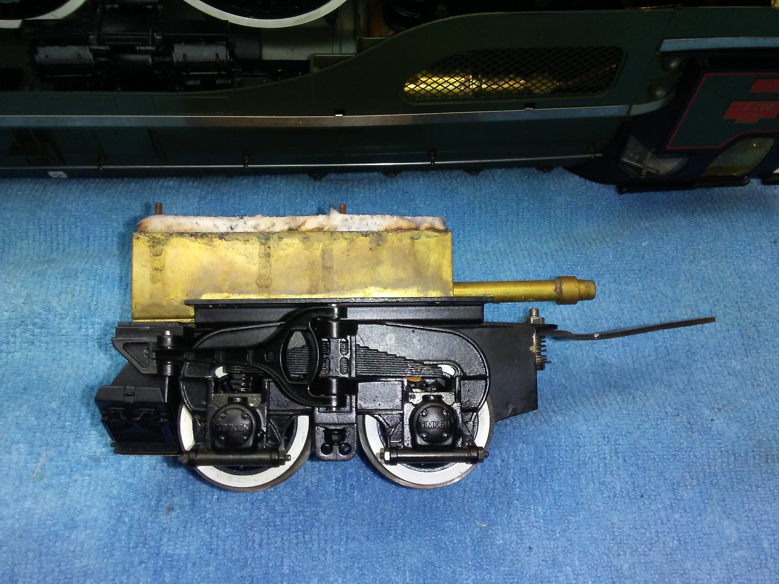
Detail view of left side drag/control link: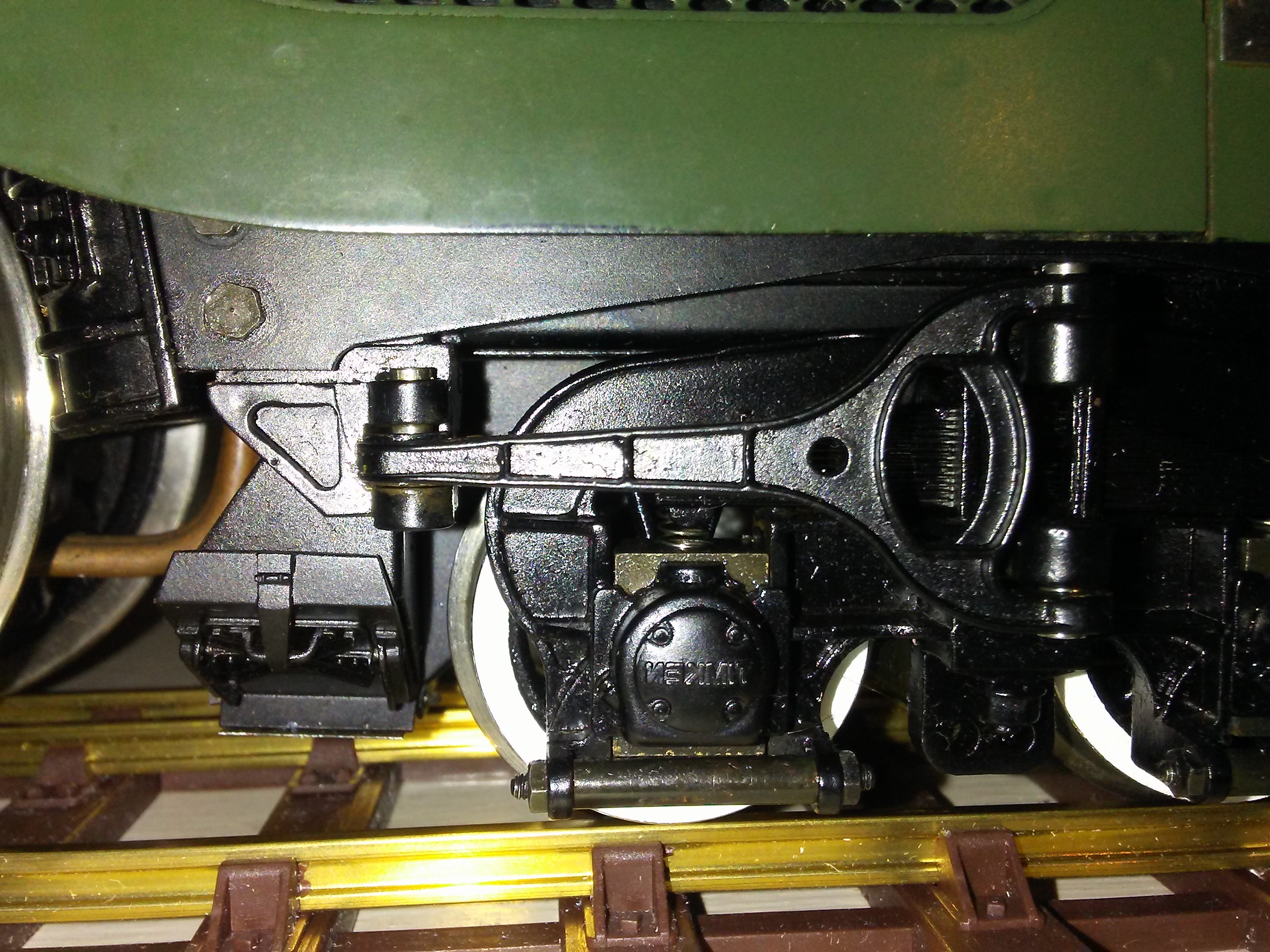
And now to a very special feature of a small model, the wet leg firebox complete with crown sheet and stays. The hot end of the five flues are visible. The two large flues contain superheater elements. As the label in the lid states, this is NOT a toy!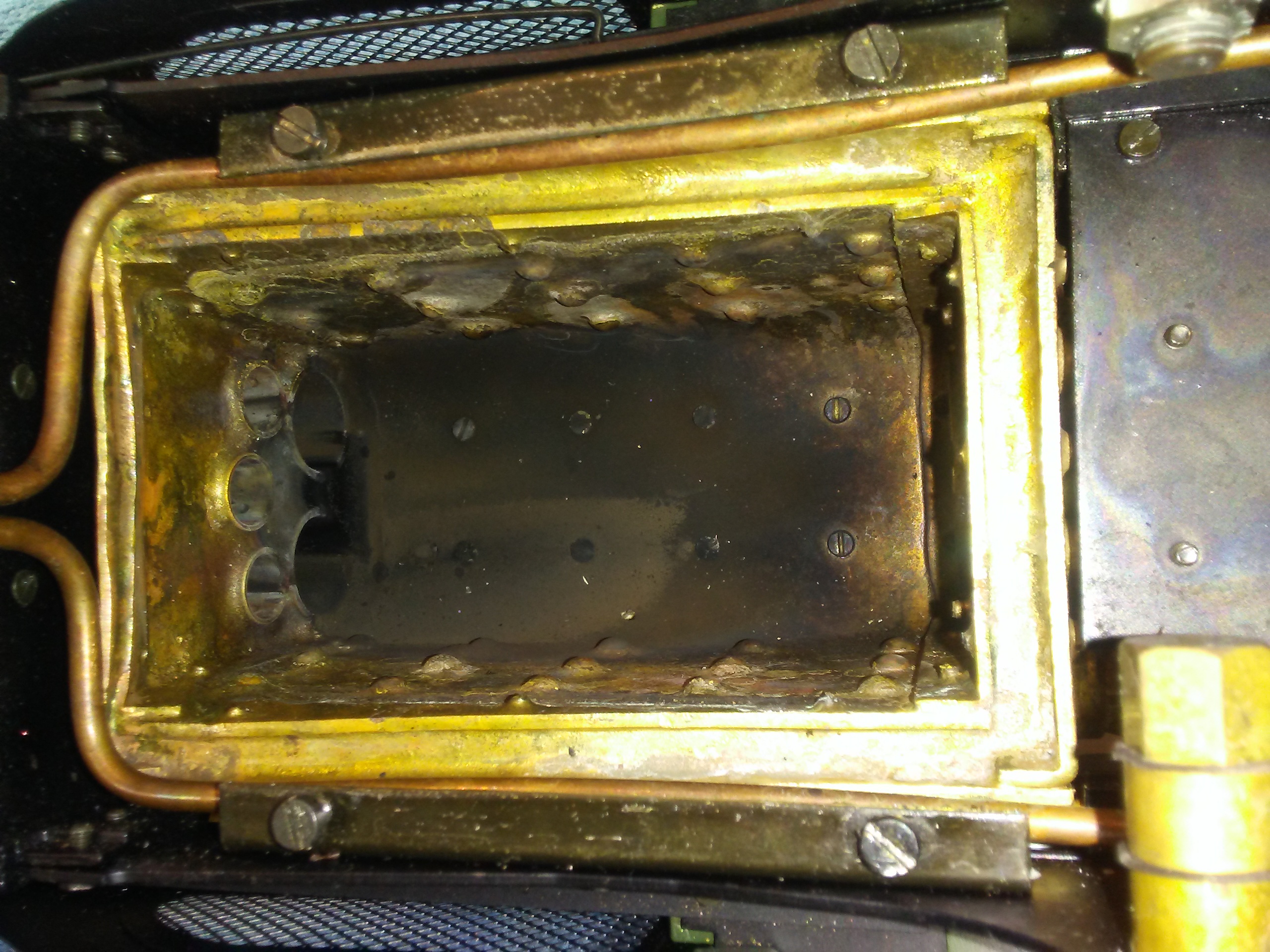
Here is the grate and ashpan in place: The four screws engage in keyholes in the side bolsters of the truck, making the truck easy to remove for changing the burner or cleaning the grate and firebox.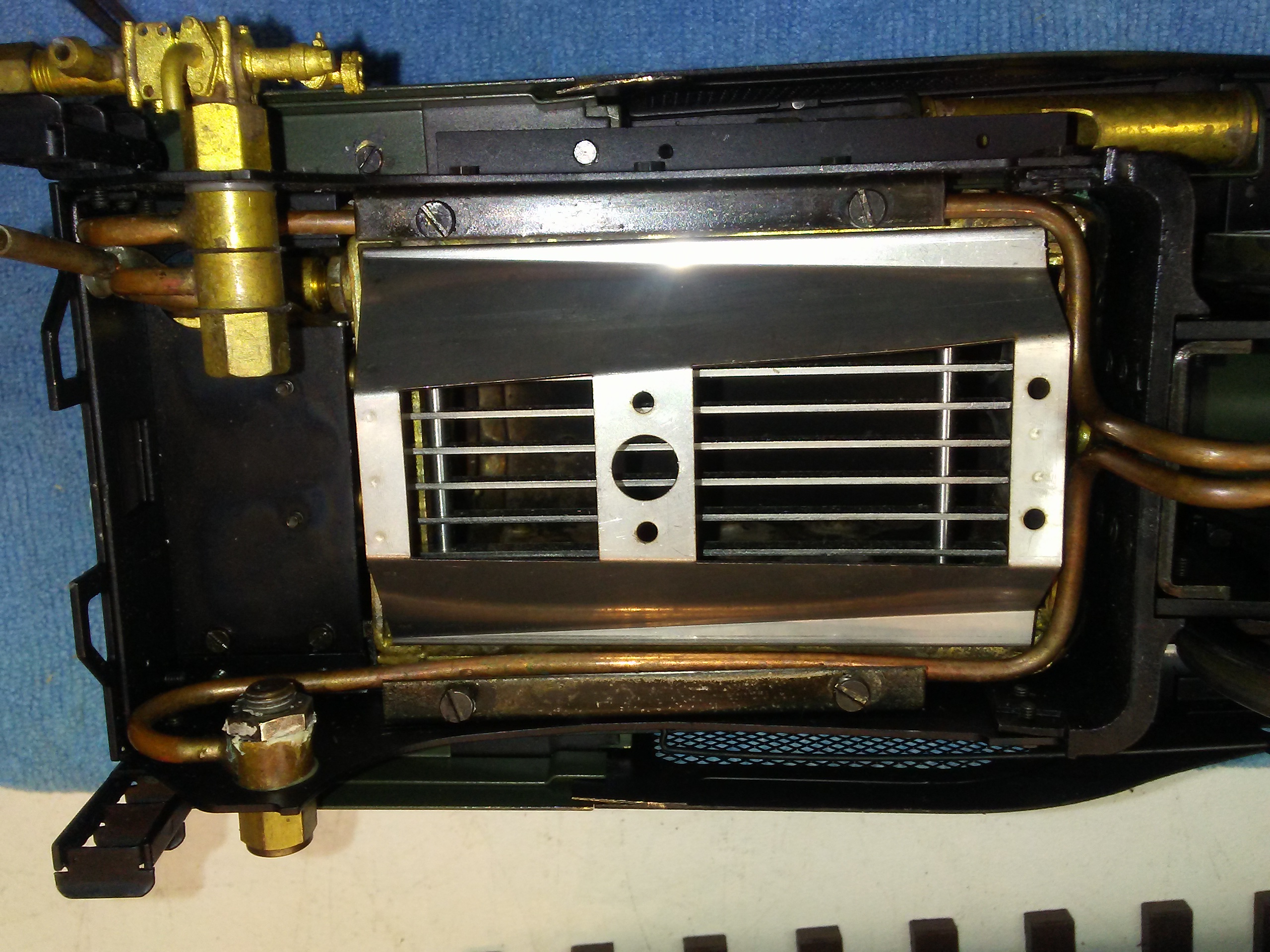
Here I’m holding one of the sprung loaded ash hopper doors open: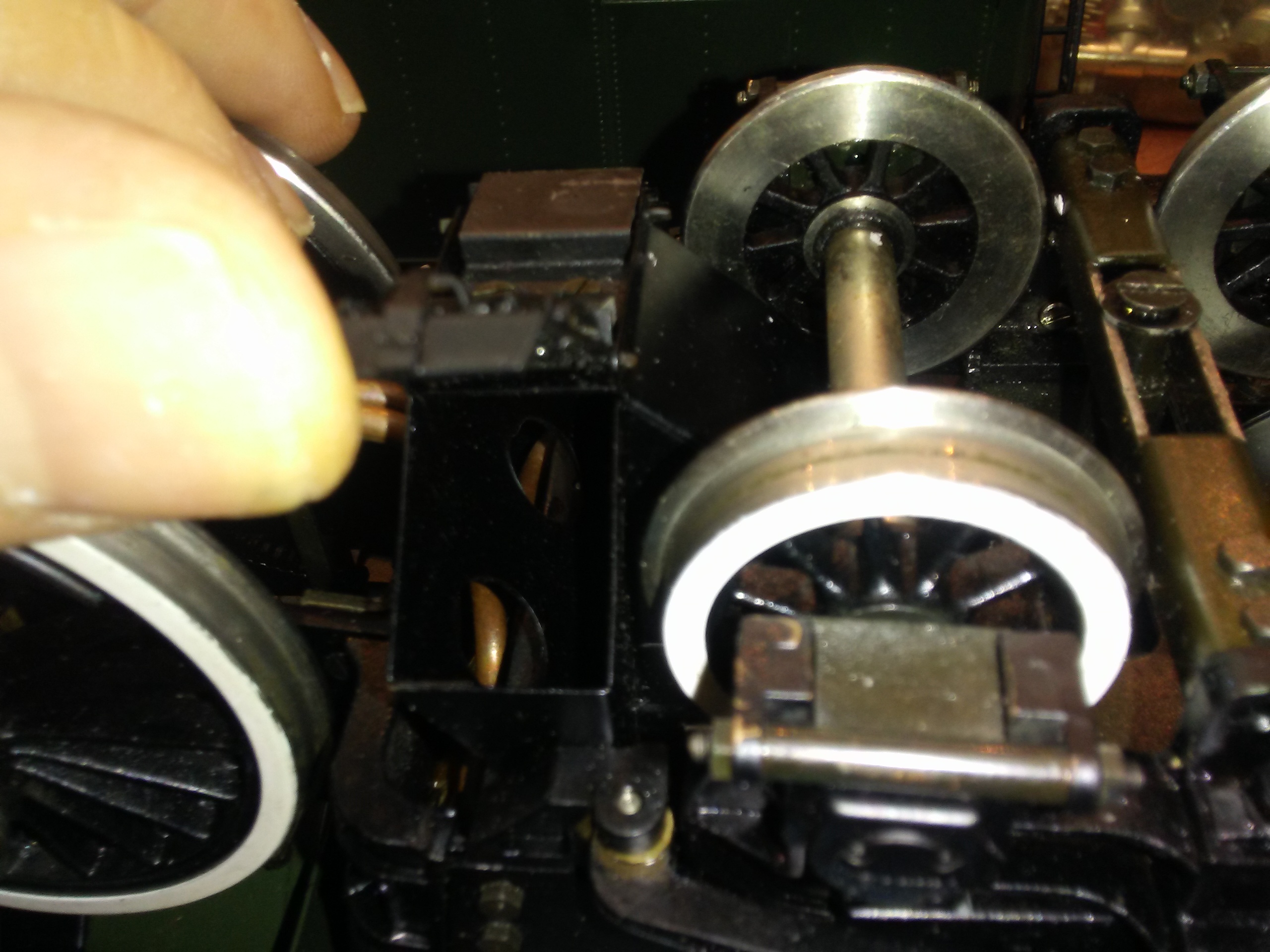
Speaking of flues, here’s a view through the firedoor into the smokebox: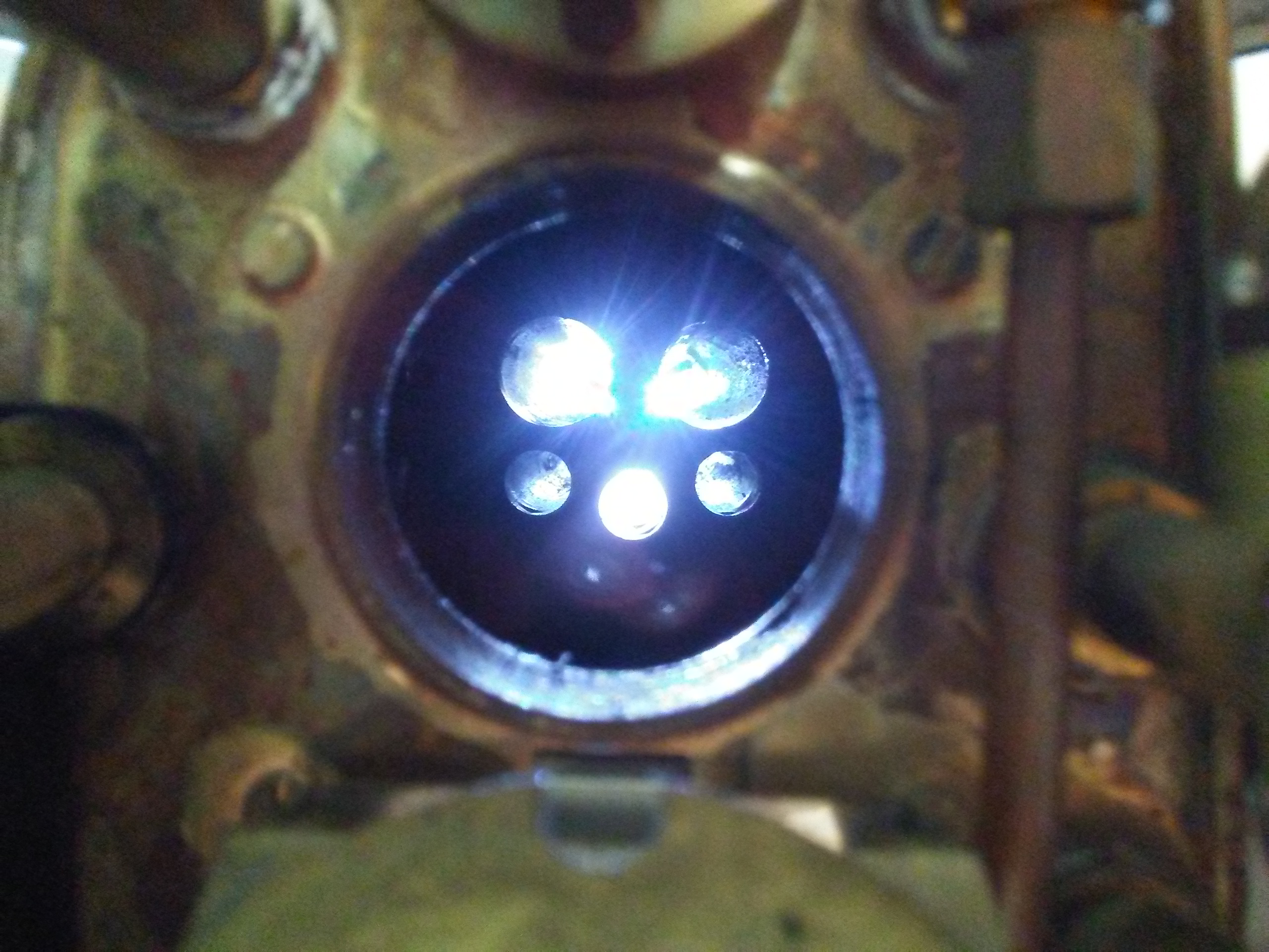
Here’s the backhead. Clockwise from top left, whistle, regulator, gauge glass, pressure gauge, screw reverser and blower. Tucked down in the left corner is the control rod handle for the LP cylinder drain cocks. At the bottom right is the feed water bypass valve. The reason for the feed water bypass is that the maximum capacity of the feed pump is designed to keep ahead of the steaming rate. There is a pump bypass valve that can be adjusted to balance the feed, the excess being returned to the tender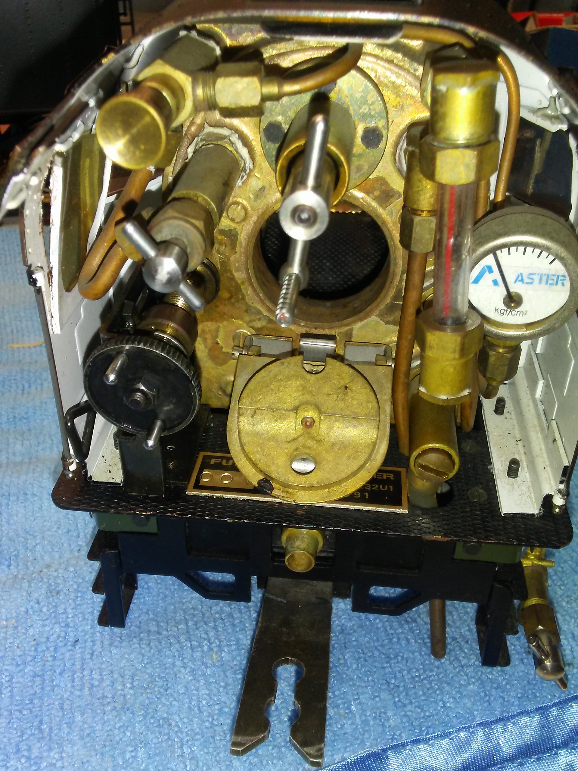
Another view of the backhead and cab: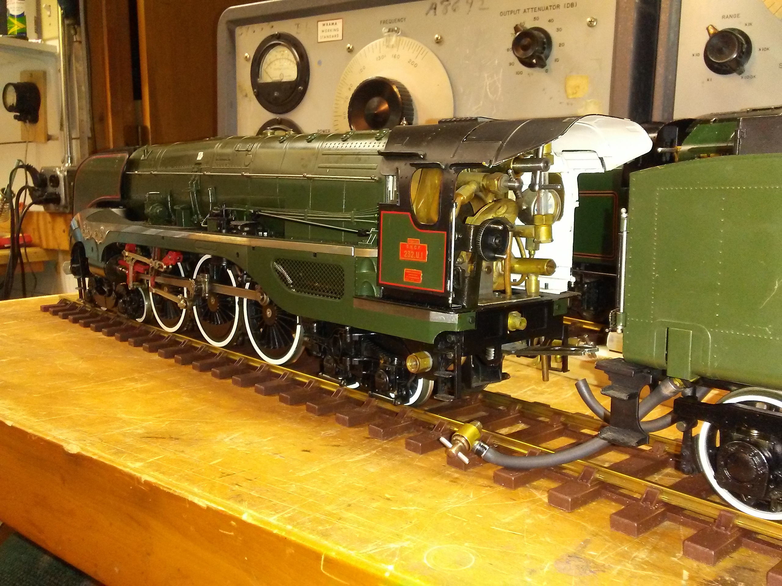
At the front end, here’s the appropriately filthy inside of the smokebox!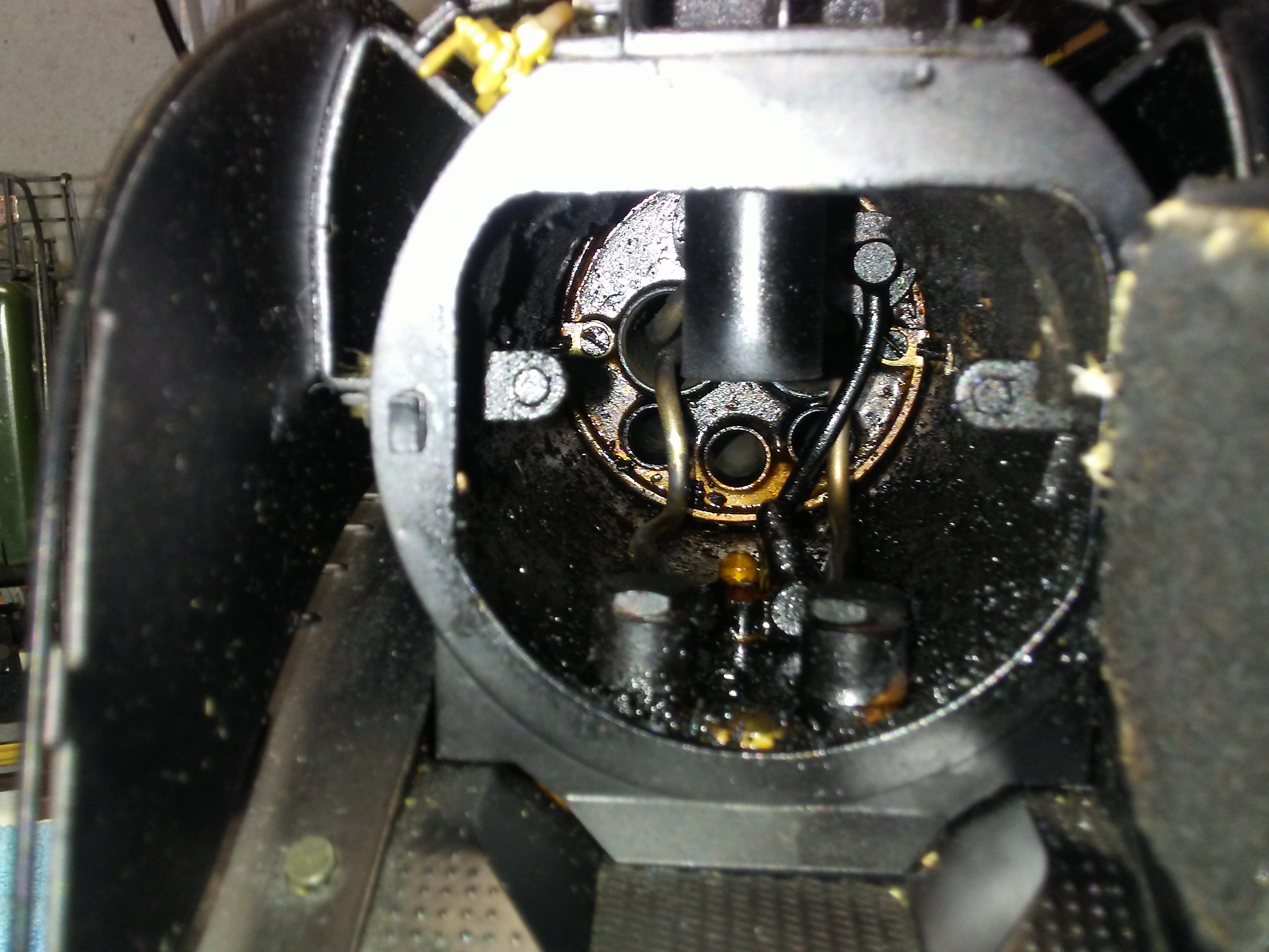
Double chimney: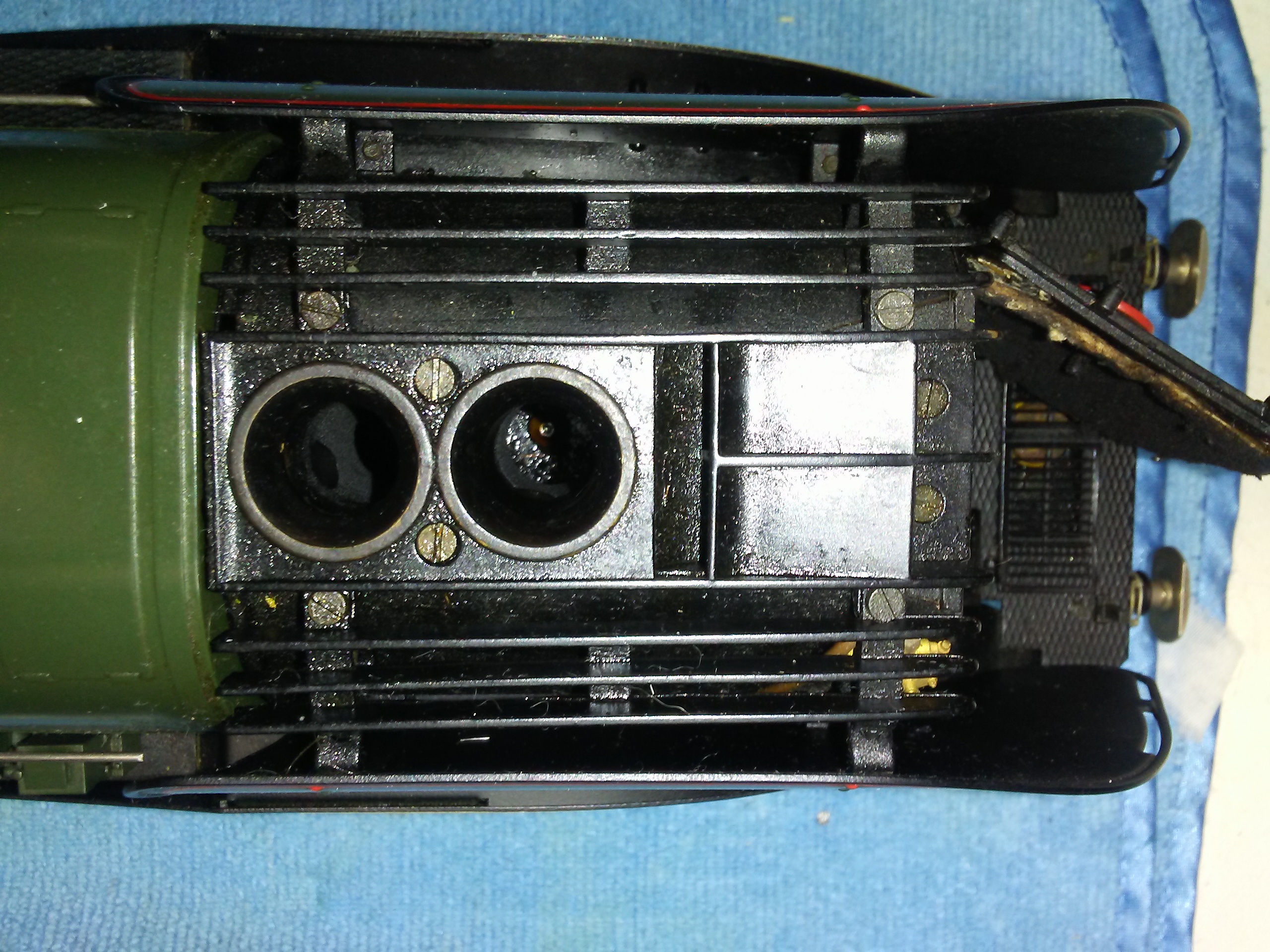
Top of boiler showing nicely detailed access flaps, presumably, some would have been for sand. The front one has been used to cover the boiler fill plug. Two safety valves (4.5bar) at the right.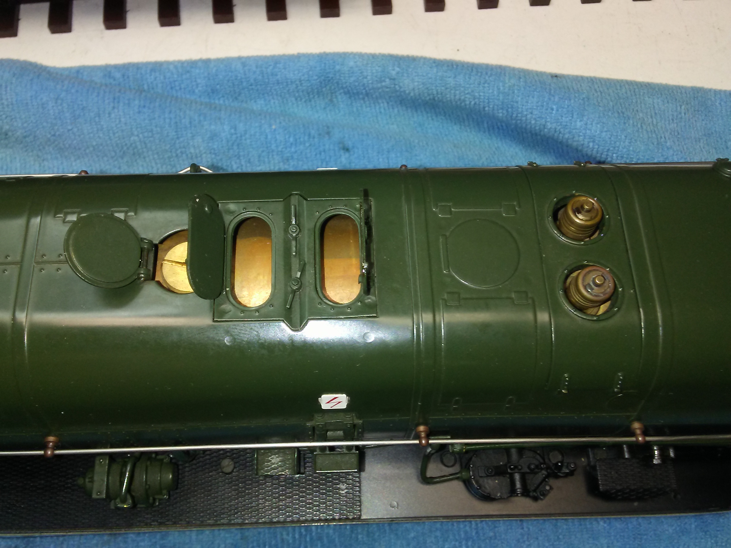
And back to the tender, it is hefty!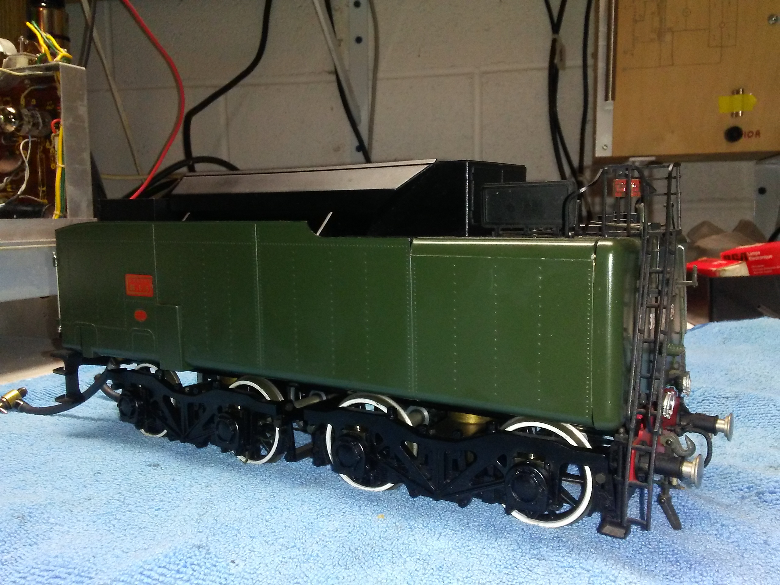
Detail view of the steps showing the catenary warning!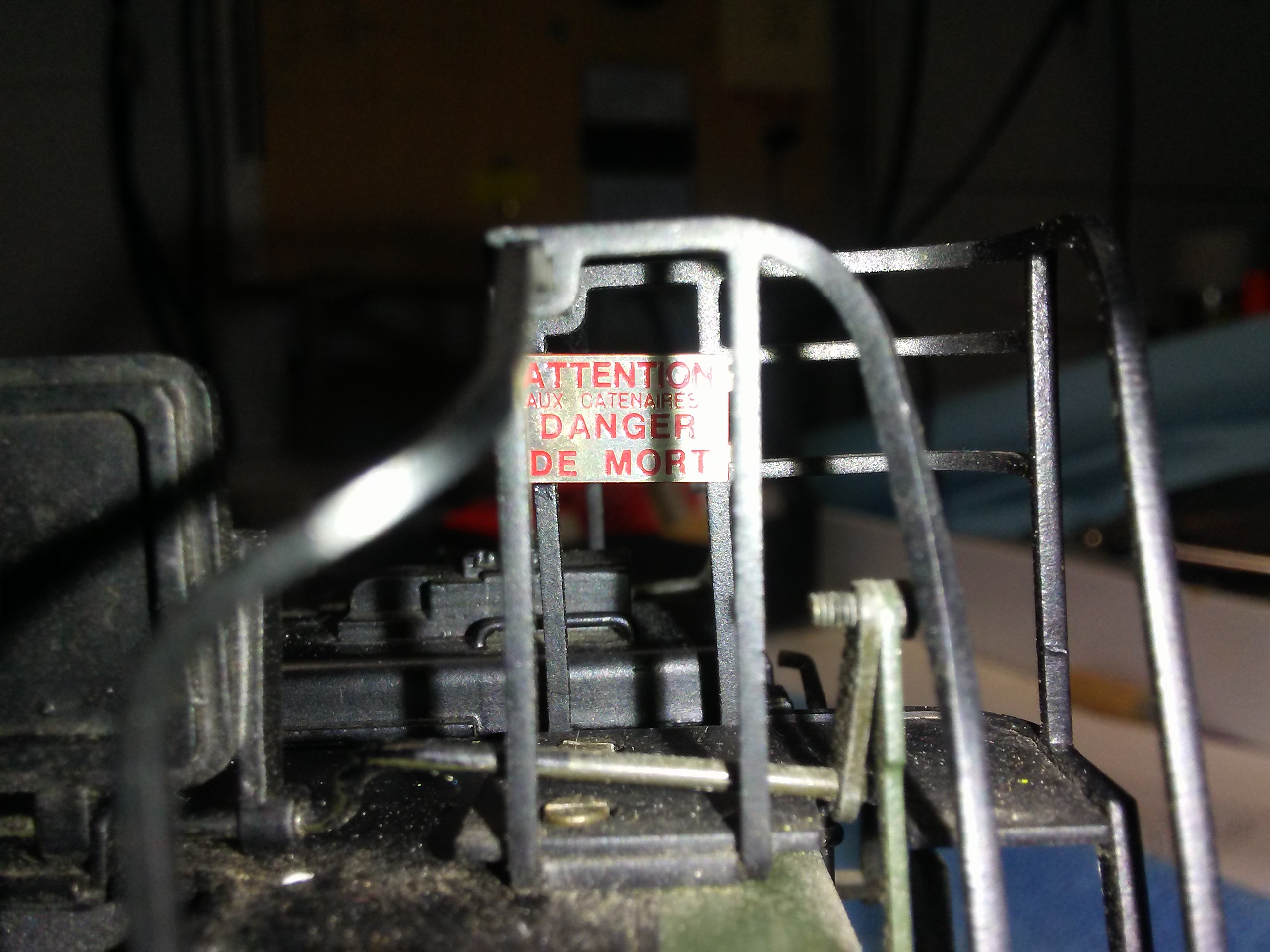
Hatches showing water tank and hand pump, again superb detail: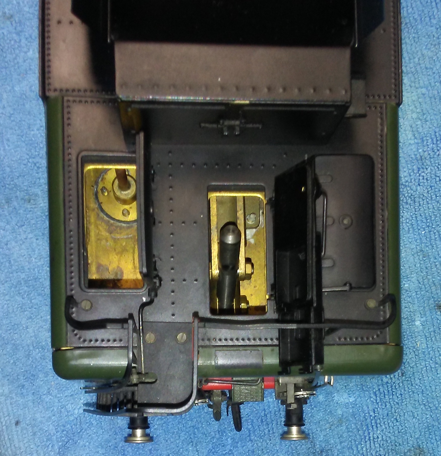
And finally the tender front showing the water bypass return, spirit connection and water feed connection. 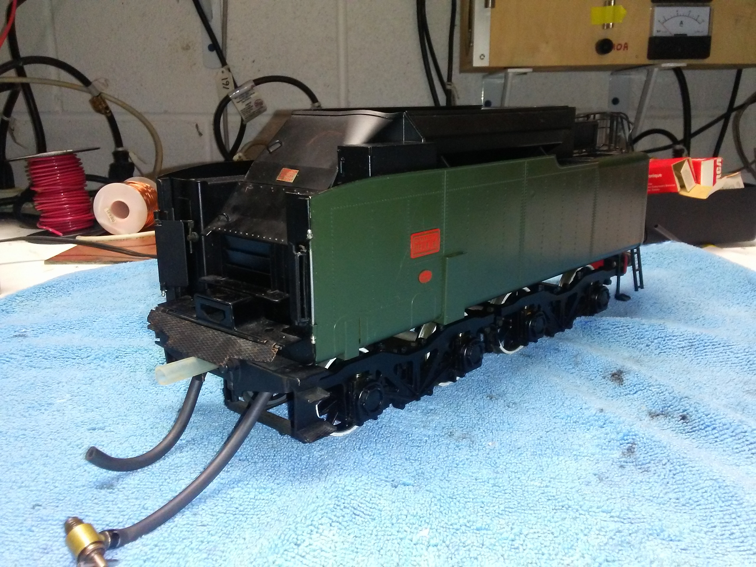
I will close with the words of John van Riemsdijk written in 1997 and taken verbatim from the Gauge 1 Model Railway Association book “Modelling in Gauge 1 Book 2”:
“The latest, and perhaps last, compound was the French streamlined Baltic, SNCF no 232U1. Baltic, not Hudson: the first 4-6-4 tender engines were also built for the French Nord main line, and in 1911, and were called “Baltics” because that was where the trains they were meant for ended up. 16 years later, the Americans took up the 4-6-4 wheel arrangement and called it a Hudson, but U1 is definitely a Baltic. The real engine proved one of the greatest locomotives of all time, and is on view with one of the original Baltics in the museum in Mulhouse. The model is unsurpassed and perhaps unsurpassable. It has only two sets of valve gear, but this is extremely robust and closely copies the same arrangement on the real engine. As compared with the Chapelon Pacific, the cylinder sizes are the same, but the greater weight of the coal-fired boiler improves the adhesion and allows higher working pressure to be used effectively. There are drain cocks on the L.P. cylinders, but I find that it clears itself without their use. In fact you can tie it onto a very heavy train, then raise steam, and when at full pressure the engine will quietly move off with its load, the puff only becoming audible when the cylinders warm up.”
Please Note: If an official of the G1MRA feels that I have appropriated these words err, inappropriately, notify me and I will (reluctantly) remove them.
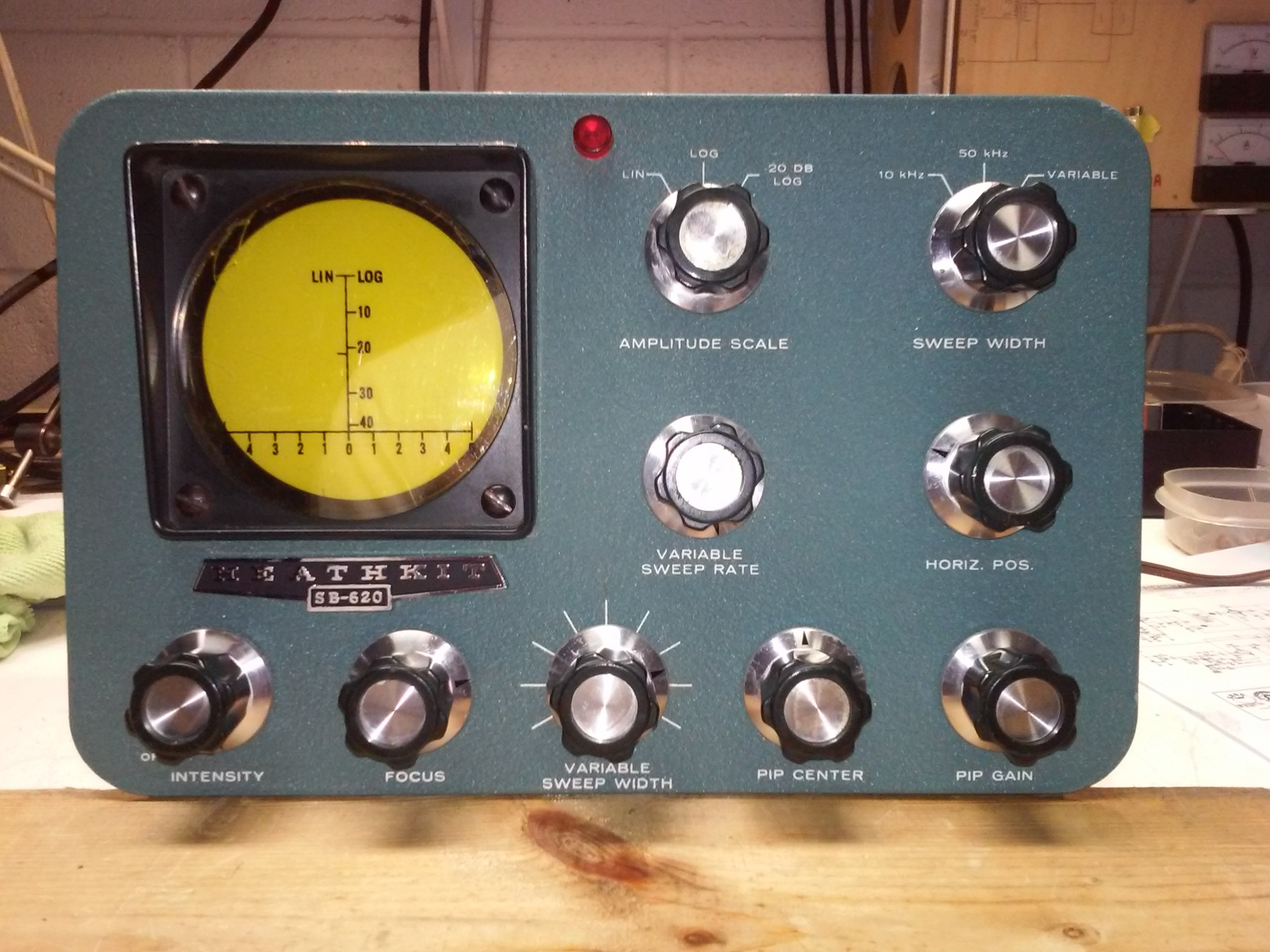 Despite my interest in vintage electronics now taking a back seat to other things, I have been interested in obtaining one of these for a while and recently acquired one, a dead one. These devices are usually known as Panoramic Adaptors and were used by the Signal Corps. There was another well known commercial one suitable for radio hams but I cannot recall who made it and a quick Google search hasn’t helped.
The purpose of the device is to allow a radio operator to see what’s going on close by the frequency he is working or considering working, out to +/- 25kHz or so. Functionally, it is a narrow range spectrum analyzer. The fixed ranges are 10kHz and 50kHz, a variable range allows the unit to scan out to +/- 250kHz or slightly more, depending on the IF frequency of the receiver it is looking at. There were different coils available for the local oscillator and a builder/ user would have to set the LO up for the IF frequency of interest. In my case, I have a Heathkit SB-102 that has an IF of 3395kHz and fortunately the unit I have was set up for 3395kHz though apparently with the wrong oscillator coil, more on that below.
It has turned out to be one of the more interesting pieces of kit that I have encountered. The operating principal is the use of a frequency changer (mixer) and a sweeping local oscillator. The oscillator is swept by a voltage that is derived from the X axis sweep voltage and applied to a varactor diode. As the oscillator sweeps, when a signal is present that causes a difference frequency of 350kHz that signal is passed by the IF strip in the analyzer, is then rectified and presented to the Y axis. The signal being synchronous with the X axis results in a stationary peak or a “pip”. There is a crystal filter before the IF strip that sharpens the resolution to 1kHz. The sweep is generated using a neon relaxation circuit.
The first job was to bring the thing back to life. There was a poorly patched in replacement CRT negative supply capacitor that did not bode well and sure enough there was no HV-. I soon established that the corresponding transformer winding was open. This is actually helpful in an odd kind of way because such failures are usually (in my experience) due to insulation failure and that means the transformer is rendered completely useless. I took the transformer apart far enough to discover the remains of a burnt lead out from one end of the winding. I surmise the winding burnt when the aforementioned capacitor failed. So the transformer could still supply the B+ and heaters, all I had to do was to sort out a work-around for the HV-. I wound up (pun intended) making a voltage quadrupler that would be powered by the B+ winding. Even with current draw multiplication due to the quadrupler, since the HV- chain only draws around 200μA the additional load on the B+ winding is negligible. However there was still an issue. Because the B+ is also rectified by a full wave doubler, the B+ winding is elevated some +250V and if I connected directly, that elevation would subtract from the negative HV. So I capacitor coupled the system to the B+ winding. Further it is necessary to connect the correct side of the chain – marked “A” below – to the top end of the B+ winding otherwise it will not work. Here’s a picture of each side of the quadrupler with the diagram: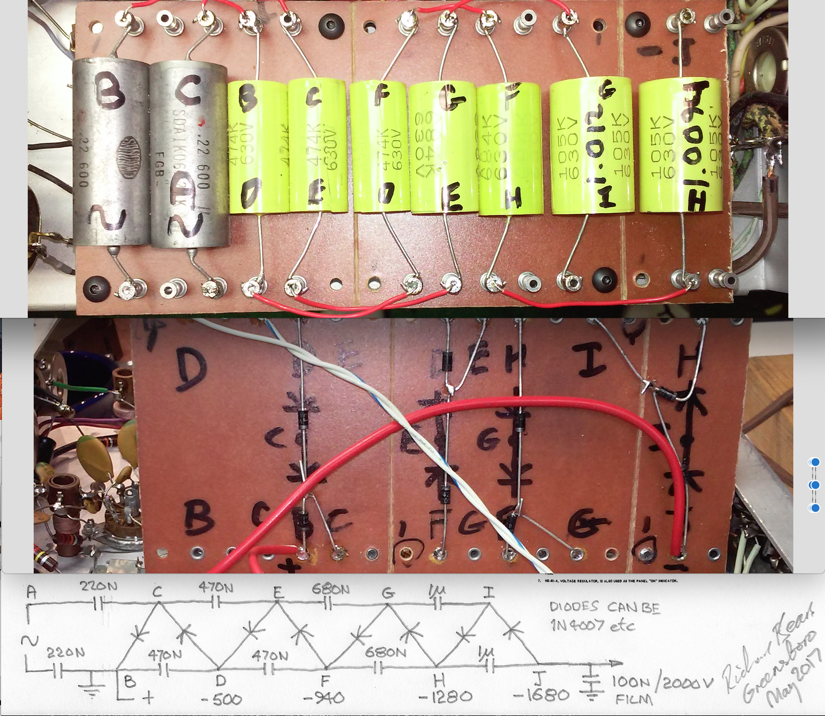
I found it necessary to increase the value of the caps for each stage to maintain the successive voltage gain, you can see from the measured voltages noted on the diagram that the chain steps fairly uniformly to the desired voltage. It worked out perfectly! It also fitted perfectly: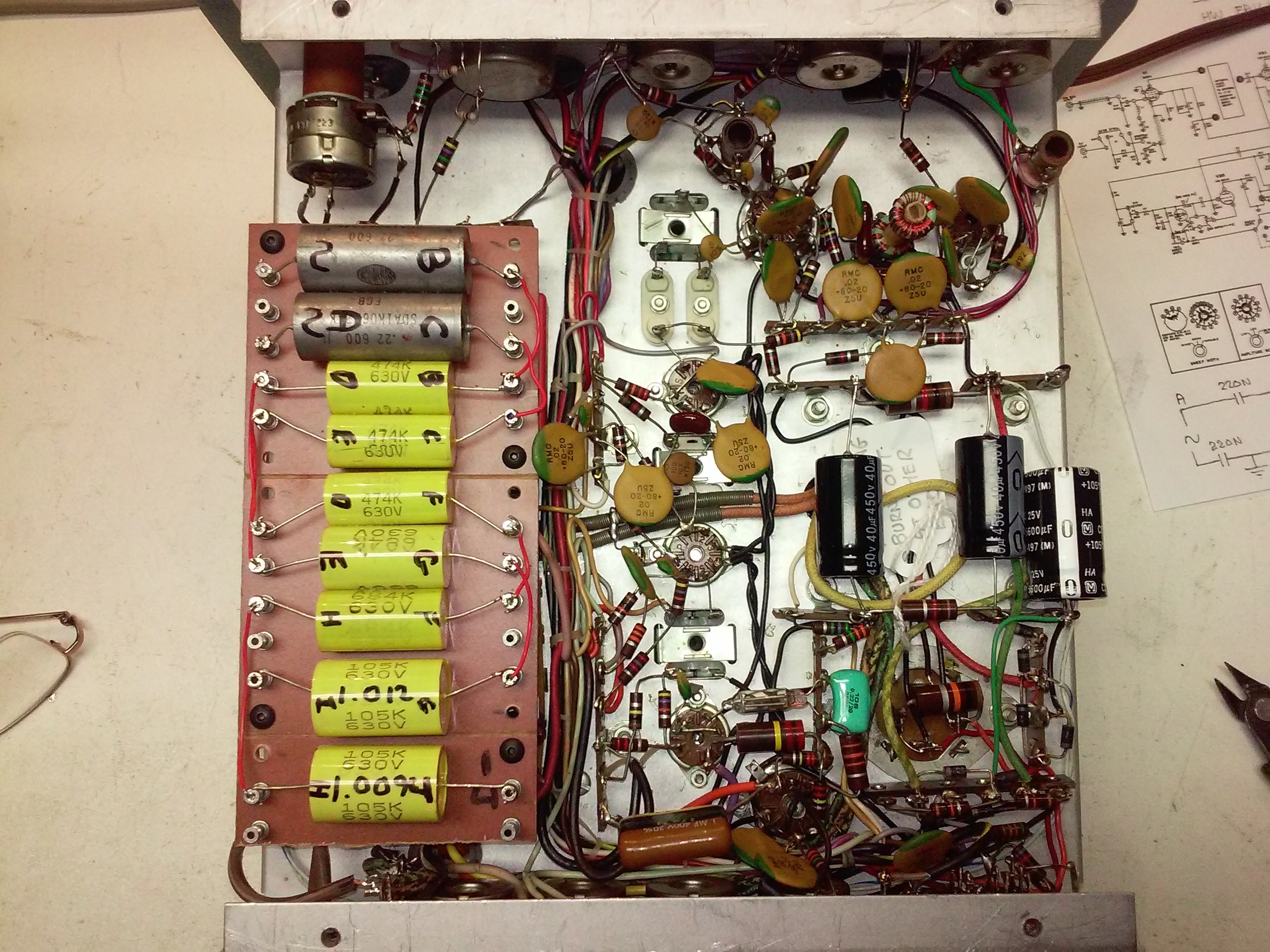
I went through the calibration protocol and encountered a problem that took a while for me to comprehend (my knowledge of RF is sketchy at best). On setting the local oscillator (LO), I found that it seemed to tune well however, the instructions go on to test whether the LO is set at the correct frequency, i.e. 350kHz under the incoming IF frequency or 350kHz over. The method is to raise the incoming frequency by precisely 700kHz and an image peak should appear to the centre of the screen. Well, it didn’t. Said another way, the LO should be 350 above the incoming IF such that if the incoming signal is raised 700, it will first pass through the LO frequency and finally be 350 above so that an image signal will pass the analyzer IF strip. I later revisited Stephen Lafferty’s notes on constructing different LO frequency arrangements (the original parts are as rare as rocking horse poo) and he noted that for an incoming IF of 3395, the LO should be at 3745 whereas mine was at 3045. I queried this claiming ignorance of matters RF and Stephen confirmed that his figure is correct. Stephen’s article is here. We went back and forth a little, both being puzzled. The problem is that the LO coil (L3) is not marked with a part number. We concluded, I think, that the coil in my unit is not correct for an incoming IF of 3395kHz. Stephen had used a trimmer for the LO tank capacitor, and I followed his lead. The coil in my unit was already adjusted close to minimum inductance and so the fixed 56pF cap had to be reduced in value to raise the LO frequency. I replaced the cap with a 7 to 47pF trimmer and was easily able to obtain the correct LO frequency and the 700kHz image per the instructions. HOWEVER, the law of unintended consequences intervened: Before making this change I had taken a picture showing combined 1 and 4 kHz modulation with the peaks occuring in the correct locations thus: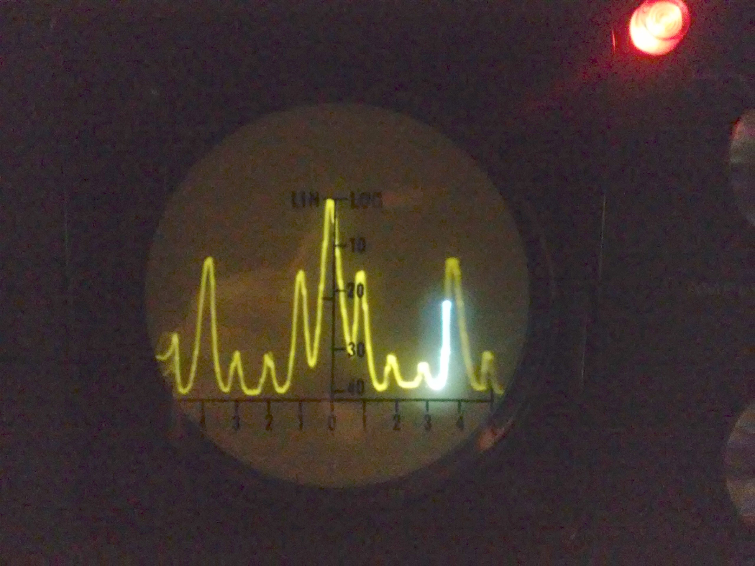
(The small pips are harmonics. Note, the pip centre control is excessively touchy on that range hence the poor positioning in the picture above. The flash is due the the scan being very slow compared with the shutter speed.) After the modification, I was unable to reproduce this result with the modulation peaks occurring at approximately 1/2 scale. After much thought (well what passes for thought in my slow old brain), I realised that the reduction in fixed capacitance in the LO circuit meant that the swing of the varactor now had increased influence, approximately double, and that the bandwidths were now double the intended settings. Rather than screwing around with the varactor swing voltage settings, I chose to increase the capacitance and settle for the LO being 350kHz below the IF frequency at 3045kHz. It just works better and is more satisfying to play with this way. Here’s what it looks like squashed up by the doubled bandwidth: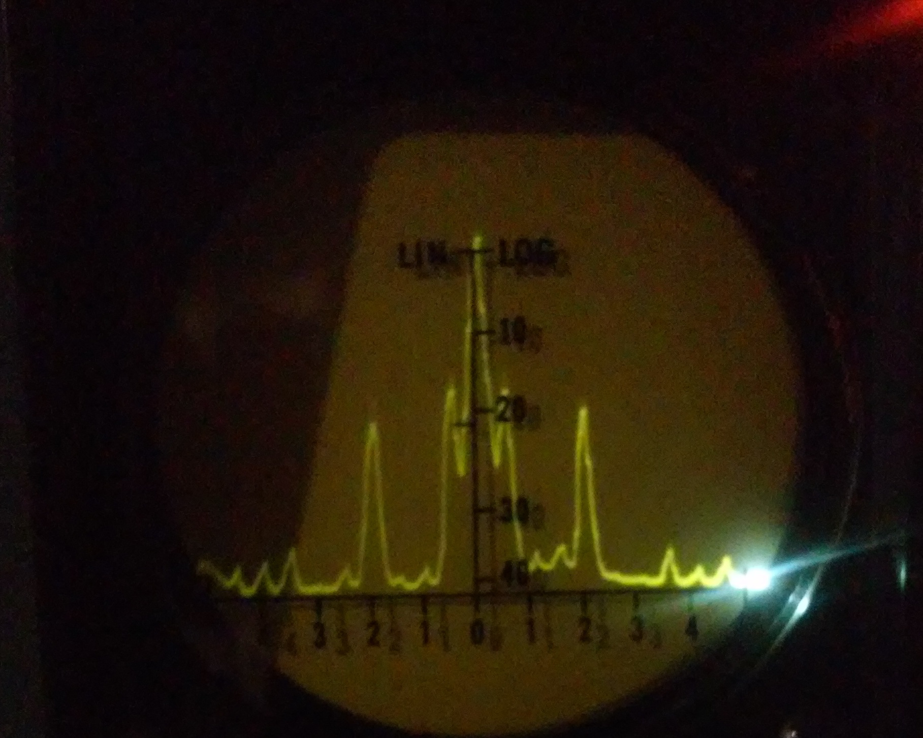 I then decided to address the excessive pip centering sensitivity; The pip centre pot is 5k. I established the resistive setting with the pip centered then replaced the pot with a 2k part with appropriate resistors each side. This reduced the sensitivity usefully while still permitting the pip to be moved to the side of the screen when using the 50kHz sweep range. Again, it makes the device more fun to play with.
The next problem was that the sweep circuit then failed on the 10kHz range. This requires the slowest sweep rate and the charging resistance is more than 100Meg, the currents being in the few micro-amp range. I checked the values of the various resistances and they were surprisingly close. I also replaced the capacitor (the green cap in the picture above) but it still would not sweep on the 10kHz range. So, once again, a puzzler. I decided to see if perhaps grid current draw from the X amp was stalling the relaxation circuit. Changing tubes didn’t work, I tried several. However, I found that both the plate resistors were almost double the specified values despite being marked correctly. They are too small in size for the job and in my experience, carbon composition resistors develop cracks when run too hot over time. I replaced them with correct values and sure enough relaxation action resumed (if that isn’t a contradiction in terms). This might seem surprising however, it’s a Kirchoff thing, the currents entering a node must sum to zero. In this case the node is the triode and if the plate voltage is too low to cause sufficient conduction from the cathode, the current to balance the node must come from the grid. (I’ve encountered this before and at that time it stumped me for a while. I was developing a hybrid cascode for a phono stage with a fet in the bottom and a triode in the top. The triode was pulling the grid voltage reference down and I finally realised that I needed to increase the plate voltage.)
The rest of the calibration is pretty mundane though I encountered another issue when the instructions direct one to amplitude modulate the incoming IF at 50kHz to set the scan width for the 50k setting. Neither of my signal generators (GR 1001A and HP 8610A would accept AM at that high of a frequency. It’s not necessary, I found that if I modulated at 10kHz, the harmonics took care of the rest of the band. It’s not a laboratory quality instrument, so the deal is to mark the scan width control for the setting that gives correct placement of the modulation frequencies on the screen and (presumably) check it from time to time. Here’s what 5kHz modulation scanned on the 50kHz range looks like, showing that the harmonics can be used for sweep width setting certainly out to 20kHz.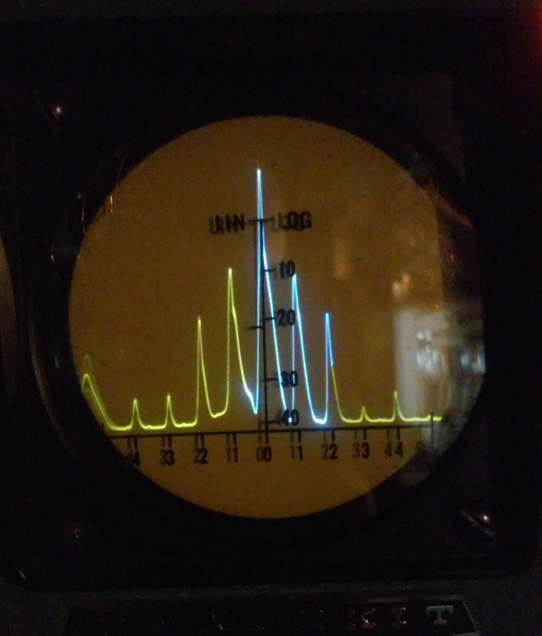
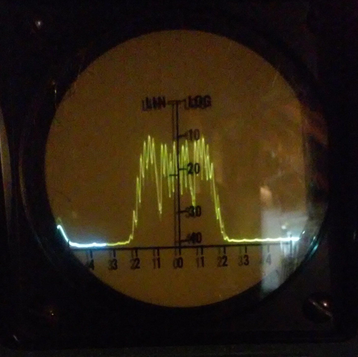
Here is what 1kHz FM looks like on the 50kHz range showing the IF passband: I didn’t understand what I was seeing and again, Stephen came to my aid: “To explain it in detail, I would need to know a little more, but generally it seems typical to me. The key question is whether you mean that the modulating frequency is 1kHz or the FM deviation is 1kHz. I will assume it’s the modulating frequency. From that, I would estimate that the peak FM deviation is 7kHz and the span of the display is 40-50kHz. (I estimated the peak deviation by counting the 1kHz peaks from the center to the edge of the deviation.) Then the modulation index is m = Fpk/Fm = 7kHz/1kHz = 7.”
I managed to get it to see the IF from my SB-102. The sensitivity is just adequate and Stephen built a 17dB gain stage into his. The noise floor does show well on mine with good peak amplitudes on quite weak signals (my antenna basically isn’t). Still, here’s something from the 40M band, the primary signal is from France: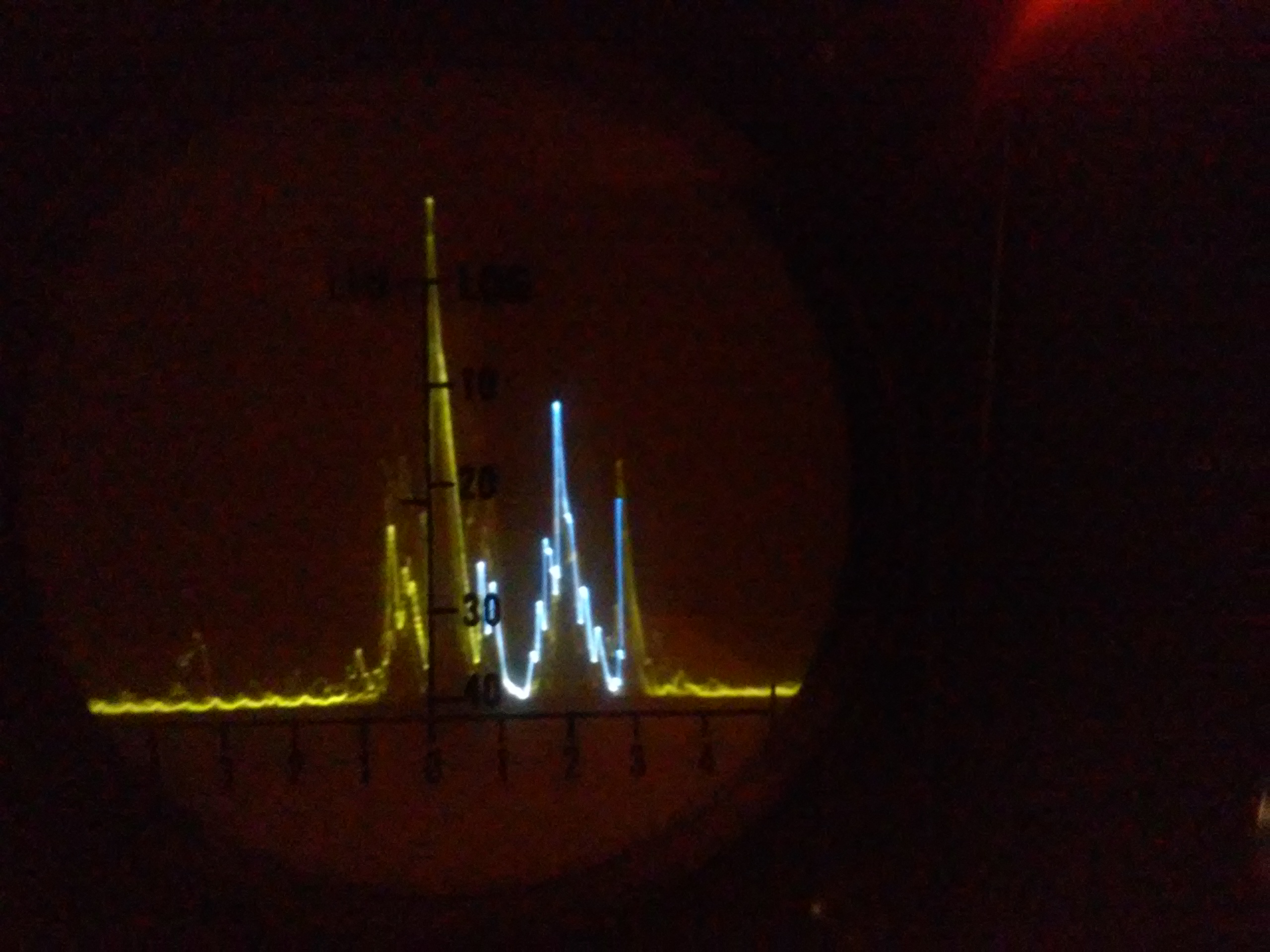
Update 7/4/16: I did a comparison using the GR 1568A wave analyser that I previously repaired and described, to locate and measure the components from the fast output of my Tek 106 square wave generator. The results from this analyser and the GR are in surprisingly close agreement, well surprisingly to me anyway. The GR is very tricky to use and I was pleased to get similar magnitude values.
HP gear is usually excellent and this unit is no exception. The other piece of HP kit that I value highly is the 339A distortion analyser that with its precision oscillator and voltmeter finds a great deal of use on my bench. Having just finished up an audio project (see Audio Audio below), I got inspired to get this working again. The last time I went to use it, the signal channel was non-responsive. As so often turns out to be the case, it was an oxidised board connector and once again, Deoxit came to the rescue! Oxidised connectors and switches are the norm in old test gear. I’m not going to go on at length, just show a few examples of it in use.
Here it is displaying the internal 10kHz test / calibration signal:
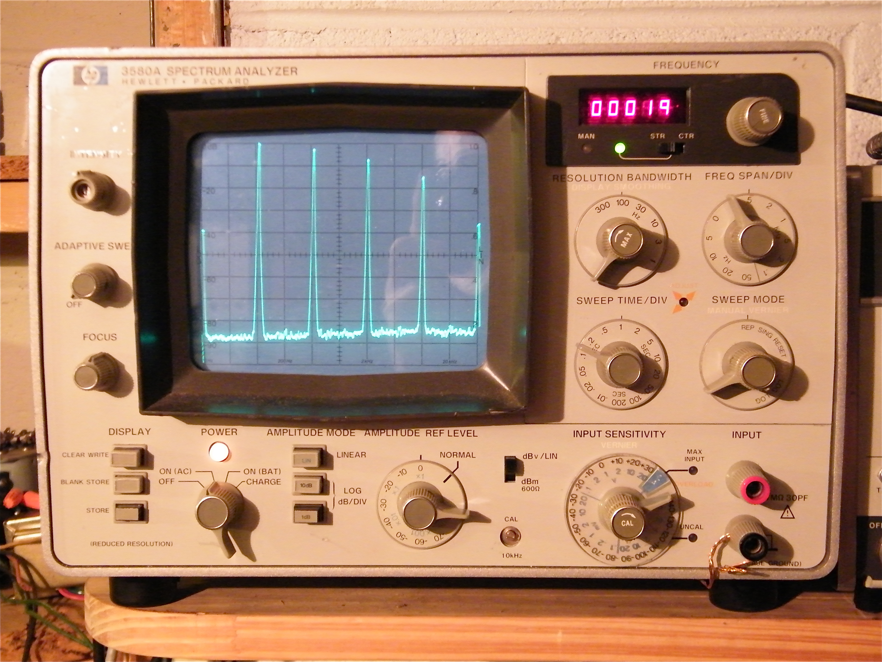
This signal can be used to calibrate the instrument within +/- 1.5% at 10kHz. It can also be used to check the frequency span which here although slightly off is within limits. The frequency range of the analyser is 5Hz to 50kHz. The spurious response is specified as more than 80dB below the input reference level and can be seen here more than 80dB down after all these years. Here, the signal fundamental at 10kHz is the first spike that can be seen to exactly meet the top of the graticule, then we have 20, 30, 40 and 50kHz harmonics.
It has the capability of digitally storing one sweep that can be brought back up after a second sweep to allow direct comparison, here is an example of that feature, comparing the distortion spectrum produced by two different types of output tube, EL34s and 807s. The “dirtier” spectrum is from the 807s. The harmonics are at 1kHz intervals on a 1kHz fundamental (far left).

The sinusoidal tracking oscillator signal, swinging from 20Hz to 43kHz is available and may be used to do a frequency response sweep. The output can be varied from zero to to greater than 1 V rms into 600Ω. The sweep start is at 20Hz, so the graticule major divisions indicate 20, 43, 98, 200, 430, 980, 2k, 4.3k, 9.8k, 20k, 43k.
Here we have the same amp with at 10W (upper) and 1W (lower). The amplitude accuracy is given at +/- 0.5dB 100Hz to 20kHz and +/- 3% over the range 20Hz to 43kHz.
It shows about 2dB rise over the range, not bad for an old school amp with less than 6dB negative feedback.

I have only shown the basic features, there are many other modes of operation. One very neat feature is that the response can be cut off using the adaptive sweep control to above the noise level and this greatly increases that scan rate. This is because the filters will search for peaks in the noise and noise basically consists of a plethora of low level peaks that makes the filters work very hard. It is very useful when tweaking a circuit to watch the spectra change with the tweaking and the analyser is running in repetitive mode. Here is the test signal displayed with the baseline raised above the noise level:

Here is a capture of a frequency scan of an inverse RIAA network:

The shape is correct but the accuracy leaves something to be desired being compressed by about 4dB. The network measures better than 0.3dB except for two point that are closer to 1dB off. Since the rest of the points (I measured 11 points from 10Hz to 20kHz) are within 0.3dB, I suspect these two points are anomalous.
I have a companion blog on audio and I have just posted a new article on an amp that I designed to use up some quality parts that I had remaining from my sojourn in the world of vacuum tube audio. As a result, the design is somewhat original and possibly actually unique. I take time to craft my articles to be both informative and perhaps, to a point, entertaining. So I do like to have them read widely, hence this notice and the link is:
https://richardsears1.wordpress.com/2016/06/30/class-a-807el34-pp-with-transformer-gain-stage/
2/27/16: Today some new Lionel Fastrack arrived so that I could construct an oval having an increased radius of 3′, (from 2′) with 5′ straights. Pulling two Ace trains Stanier carriages, a cement wagon, a cattle wagon and a guard’s van (that’s all the goods rolling stock that I have), it managed 1590′ (0.3 Miles) at a scale speed of 79mph, just short of 10 minutes run time. Not bad at all! It is something like 80 years old. This run was achieved using the operating procedure given at the end of this post.

This is one of the many “toys” that I inherited from my Dad. Bassett Lowke first issued it in 1926, it was reissued under Corgi in 2000 (or thereabouts). Until now, I have never run it successfully, nor did he. The problem was largely due to overfilling the boiler resulting in much of the fuel available being spent forcing oily water to spout out of the exhaust. This is a result of following the official directions! More on this below. Another issue was due to fuel spitting out of the fuel vent and catching fire. Such problems are common with these small spirit fired engines and many that I have seen while browsing the internet have burnt livery. Operating outdoors, it is hard to see a flare up until the paint starts to burn! ALWAYS have a soaking wet towel to hand.
The Basset Lowke recommended fuel load is 30cc and the water 150cc. Using 150cc of water, the boiler primes heavily at the start. After several runs I have found that there is sufficient water left after the fuel has gone if I use 100cc with 25cc of spirit. This reduced quantity of water does make getting under way quicker and less messy. I use boiling distilled water, boiling it means that less fuel is spent getting the water up to temperature. On lubrication, the Bassett Lowke instructions state to remove the two plugs in the lubricator and fill through one hole until oil runs out the other. This is FAR too much (about 8cc) and will completely exhaust the burner just trying to get the valves and cylinders clear. I use 5cc of steam oil.
I have counted the (18ft) laps the loco makes pulling two coaches, and the distance is 1400ft or a little over 1/4 mile. In scale miles this is 11.4 miles, quite good for a loco having no fuel and water replenishment! You may see her in action here.
Reversing is accomplished by a valve that swaps the steam and exhaust pipes around. Here’s a close up of the motion:

If the boiler is allowed to cool without any opening to atmosphere, it tends to draw in oily goop from the lubricator that will foul the inside of the boiler, impairing heat transfer. This can be avoided by opening the whistle when the burner goes out. I washed the boiler out many times using boiling water to clear this as much as I could, a lot of oil came out. If you turn the loco upside down (with the safety valve removed) put it in forward gear then rotate the wheels repeatedly using the palm of your hand in the reverse direction, it will expel the contents of the boiler via the safety valve hole.
After washing the boiler, I did the reverse process (with the safety valve installed) still using boiling water, to wash out the steam passages. I did this in both forward and reverse.
The valves and pistons have no seals instead relying on the viscosity of the oil. At the low operating pressure of 15 psi, this is completely effective, I see no steam leaks from either the valves or the piston rods. It is possible to get the pistons out of the cylinders, the rod end caps are a light press fit and may be carefully pried out if necessary. I did this during my efforts to wash out the steam circuit.
I found myself wondering about the state of the wicks in the burner. This is a simple vapourising spirit burner with a row of 16 jets (well, holes).

The wicks were in a nasty state. The carbonised mess at the top of the main wick meant that it was not wicking very well. I realised that this issue had contributed to the problem with fuel being expelled from the vent and catching fire. Even though the burn rate was far too slow, the loco would still get hot. Since the fuel was not being burnt quickly enough due to the fouled wick, the pressure in the fuel tank was rising resulting in expelled fuel. Like many things, it is all too obvious once seen. Here are the old main and vapourising wick with the type of ceramic wick material (left over from 35028 Clan Line) that I used to pack new wicks. If you replace your wicks, make sure that the vapouriser wick only protrudes something like 3/16″. If the vapouriser wick is too large, the ensuing large flame will simply rob air from the burner jet above it.

Here is the burner in the loco:

Here is the oily state of the loco after a run, at least we know that lubricant is getting through the valves and cylinders!

Ditto the lubricator:

So, to summarise, this is my recipe for operating this loco:
1/ Ensure that the lubricator is empty (see 10 below). This is important otherwise you will get oil into the boiler in the next step.
2/ Ensure that the boiler is empty, you can do this using the blow out procedure described earlier in this post. This step is to ensure that the boiler is not over filled due to adding the correct amount of water on top of residual water.
3/ Fill the lubricator with 5cc* of reputable steam oil. DO NOT use the prescribed method of filling until oil flows out of the second hole, it will be over full and the consequent hydraulic locking will make it extremely hard to start. Do this with the loco horizontal to avoid oil going into the boiler. Replace the plugs firmly. Since I changed to this method, the loco will self-start without any pushing. In comparison to how things were before I developed my own running procedure, this actually is miraculous!
4/ Add 100cc* HOT distilled water to the boiler and fit the safety valve. (BTW, the valve lifts at approximately 15 psi.)
5/ Add 25cc* of methylated spirit or wood alcohol to the burner tank, fit the fill plug firmly.
6/ Carefully install the burner into the loco. The jet bar goes up between the second and third axles. Ensure that it is locked in place.
7/ Using a taper through the rearmost slot in the frame, light the vapouriser wick. Wait about a minute and similarly, light the burner using a taper through the middle slot in the frames. You will need to light up in the shade otherwise it is impossible to tell when the burner has caught.
8/ KEEPING YOUR HEAD WELL AWAY FROM THE TOP OF THE LOCO, Place it on the track and wait. When the loco tries to move, if necessary, you may help it to expel the condensate by pushing it from behind! However try waiting another minute, the loco may self-start.
9/ Open the whistle when the burner goes out. Leave it to cool.
10/ Once the loco has cooled, remove one of the plugs from the lubricator. Put it in forward and holding it front down, turn the wheels in the reverse direction using the palm of your hand to expel any residue from the lubricator.
11/ Replace the lubricator plug and remove the safety valve. Now, holding the loco upside down, turn the wheels in the opposite direction to the reverser setting and expel the remaining water from the boiler. This will ensure that the boiler is not over-filled the next time you fill it.
* These quantities were arrived at through many test runs. I purchased two ACE Trains Stanier coaches that are quite heavy and it was necessary to further refine the quantities, especially the oil. I made ABSOLUTELY SURE that there was water left in the boiler once the burner was exhausted. I also made sure that there was oil left in the lubricator. If you follow my guidance, it is UP TO YOU, to ENSURE that you have water left once the burner is exhausted. Do this by starting at 150cc and them come down in 10cc increments. I would no go below 100cc, the loco raises steam quickly and runs beautifully when starting from this level.
SAFETY! ALWAYS have a soaking wet towel to hand. This will save your loco and maybe more in the event of a flare up.
Suitable size O rings may be used to replace the fibre washers if they are torn.
Enjoy it running!
11/26/17: My friend Barry Coward visited from England and made this excellent narrated (by yours truly) video of the steam raising process and running this loco.
6/16/17: Radio Control:
I fitted RC to the blower and regulator using electronics from Peter Spoerer in England. He has a neat purpose designed controller, I couldn’t stomach the idea of using one of those freaky video game contraptions. Here is the mounting bracket for the actuators and linkages that I contrived: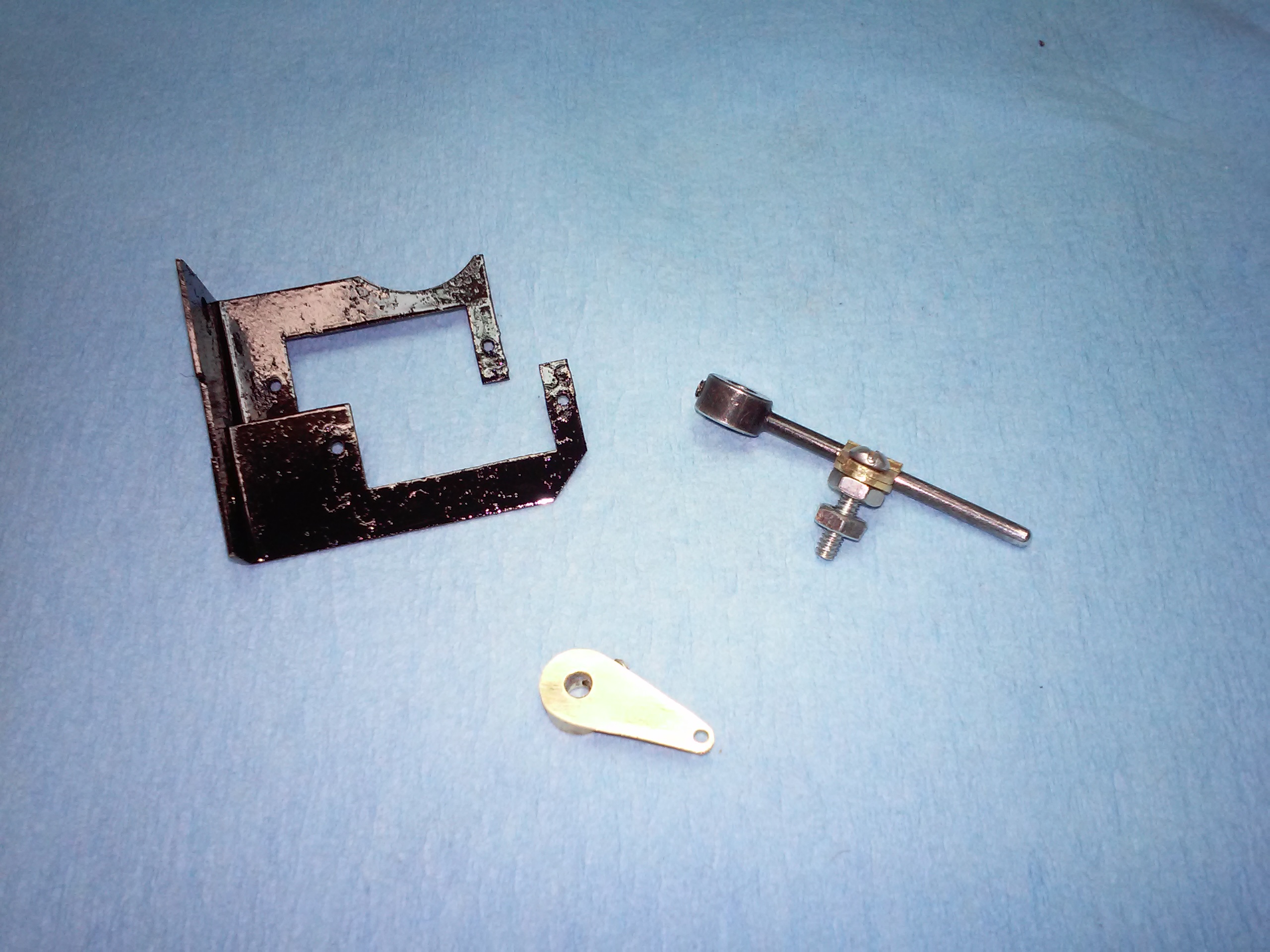
Here’s the installation: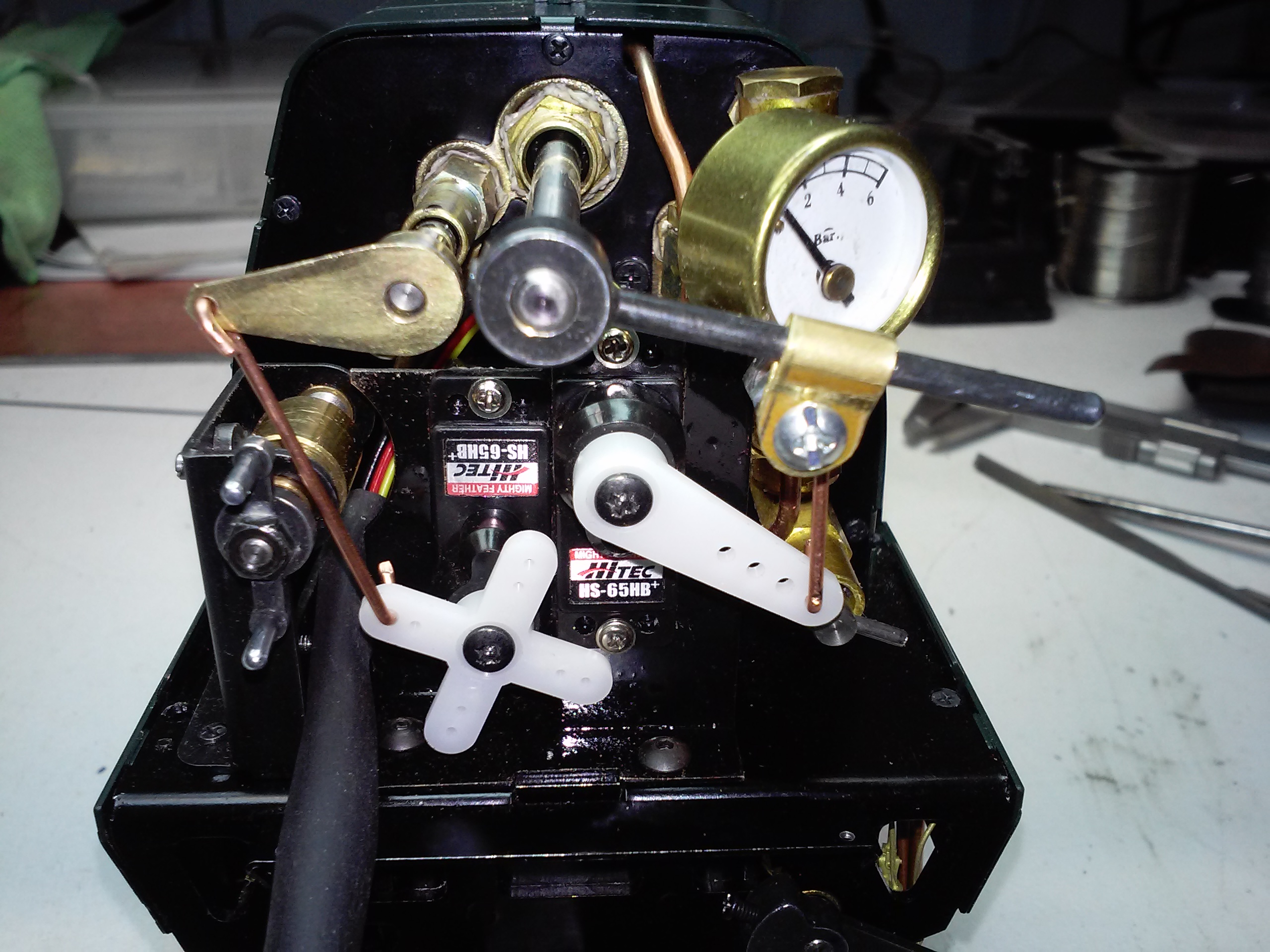
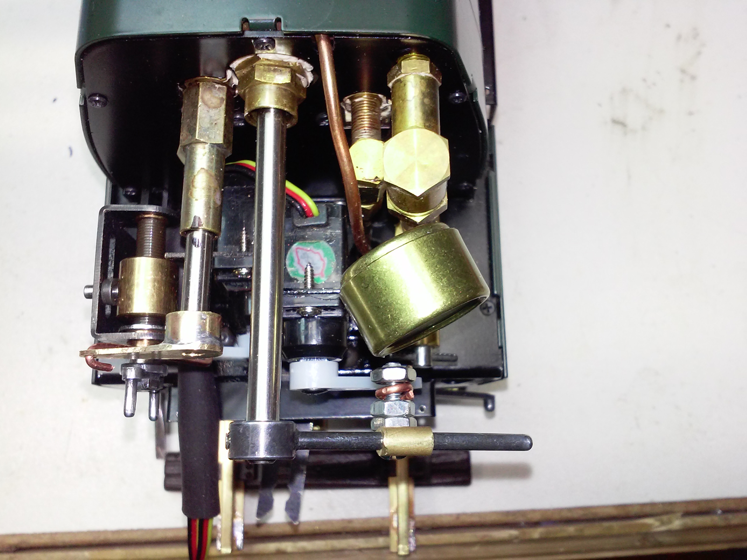
I didn’t RC the reverser, I don’t see myself wanting to reverse this loco and having 3 sets of valve gear, it is known that the gear is too stiff for an actuator that will fit in the small space. Here’s Peter’s neat controller and the receiver. The blower is on S1 and the Regulator is on S2: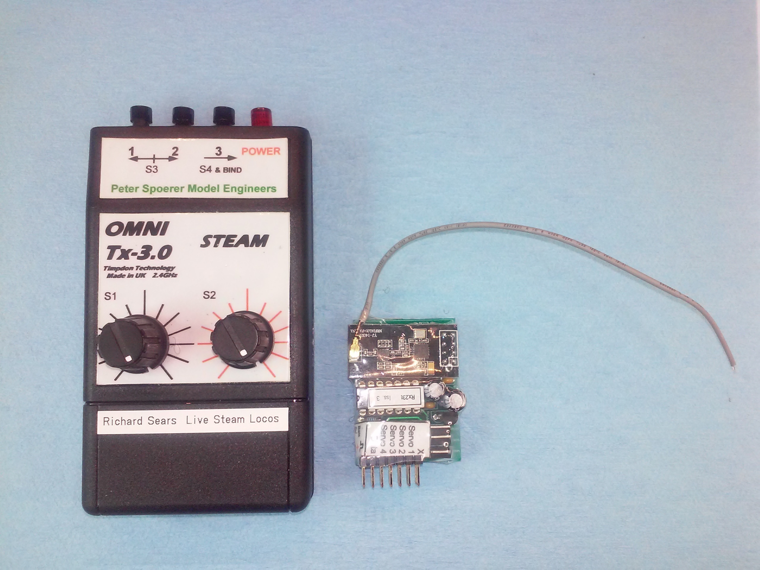
It has made the loco more fun to play with and easier to bring to a halt! One important aspect is the ability to slow it right down to check the water level in the tender and pour some more in if necessary. It usually is necessary, like the original, it is both powerful and greedy! The receiver and battery are held into the sides of the tender using self adhesive velcro. There is just enough space between the tender sides and the lift-out fuel tank.
5/19/17: Here she is breasting the 1/100 summit on my track with 10 on, you can hear the 3 cylinder exhaust beat: The loco is powerful and easily manages the 10 coaches up 50′ at 1% and reverse curves.
5/22/16: Click here to See it pulling 10 BR MK1’s on my recently completed track. The track is 155′ around and rises 5″ up the reverse curves, falling down the straight in both cases roughly at 1%. Because of the topology, it is almost 5′ off the ground at the highest location. I did build in about 4 degrees of super-elevation in all the curves.
10/05/15: INTRODUCTION. I have indulged a desire long postponed, and that is to have a high quality working model steam locomotive. Though I do have the skills, I have realised that I am not willing to commit the time (several thousand hours) or the money for machine tools to build from scratch. Having got this clear, I decided to purchase a kit and assemble it. Though I would prefer 5″ gauge, such machines are extremely costly so having been watching the gauge 1 scene (1:32 scale, width between tracks 45mm) for several years, I decided to purchase a rebuilt Merchant Navy (RMN) kit for the princely sum of $5600 from Aster Hobbies who have been producing gauge 1 live steam models for the last 40 years or so. The models are produced in limited runs and I got lucky in locating the kit for this model (in England). Well, here she is, 35028, Clan Line.

I was born in 1957 and steam ended on the Southern Region in England in July of 1967 with 35023 Holland Africa Line hauling the last down steam train from Waterloo to Weymouth. She had “THE END, THE LAST ONE” written in chalk on the smokebox door. We lived in Farnborough, about 1 mile away from the main line from Waterloo. I can remember Bulleid Pacifics tearing through, 100mph speeds were known, a couple of times officially too! I once met a man who used to fire on Merchant Navies and he told me that though it was not sanctioned, 100mph speeds were not unusual. He quit the railway when disiesel came, too boring for an active, “up and at it” type. (Almost all British steam locomotives, being relatively small, were hand fired.) While I appreciate the sheer audacity of Oliver Bulleid in his design for the original “Spam Can” Pacifics in both Merchant Navy and West Country/Battle of Britain guises, (the later being referred to as light Pacifics having greater route availability), I think that the rebuilt locomotives were and still are, the finest looking loco’s ever, bar none. These locomotives have three cylinders each having a set of Walschaerts valve gear (unlike the Gresley Pacifics that had outside gear only, the motion for the the middle cylinder being derived from the outside gears using a system of levers.) The unrebuilt loco had outside admission cylinders and the outside cylinders were carried over into the rebuilt loco’s. The use of slide valves for the model naturally leads to outside admission and so the appearance of the valve gear having the radius rod connected to the combination lever below the valve spindle is correct. Forgive me but if you find all this baffling, I do give a basic explanation of the valve gear further into this narrative.
(The use of three or four cylinders was common British locomotive practice to overcome the cylinder diameter limitations imposed by our restricted loading gauge. Other than power, a big advantage of multiple cylinders, especially three, is that smaller balance weights for the reciprocating masses are required resulting in less forceful hammer blow on the rails* and thus greater route availability. The downside is horrible access for maintenance and oiling. The driver would have to get underneath the loco between the frames to oil the inside motion. I have never read of an accident occurring….)
*As a balance weight – located inside the rim of each driving wheel – comes toward the rail and then retreats the vertical component of the motion momentarily ceases, imparting an impulse to the rail just like a hammer blow. Damage to the tracks from this effect was known with large 2 cylinder American passenger locos when pressed to the very high speeds of which they were capable. The superb N&W J class 4-8-4 when tested on the Pennsy reached 110mph, and track damage resulted. (Note: No 611 is preserved and currently in steam. I was blithely unaware of her overhaul at Spencer shops NC and living in Greensboro NC on the route back to Roanoke, could have seen her in steam. Drat. I have been to Roanoke twice over the years just to gaze at her.)
A good reference source for all things Bulleid Pacific is “Bulleid Pacifics At Work” by Col. H.C.B. Rogers OBE.
CONSTRUCTION, Here is the box!

Here is the end of the box showing contents and serial number (141 200). A plate with the serial number is affixed to the underside of the right hand (fireman’s side) running board:

This kit requires much more work than simply screwing the parts together (using a multiplicity of tiny metric screws of various sizes). Having read the experiences of others I chose to start with the tender to get used to the instructions and diagrams:


Water tank and hand pump:
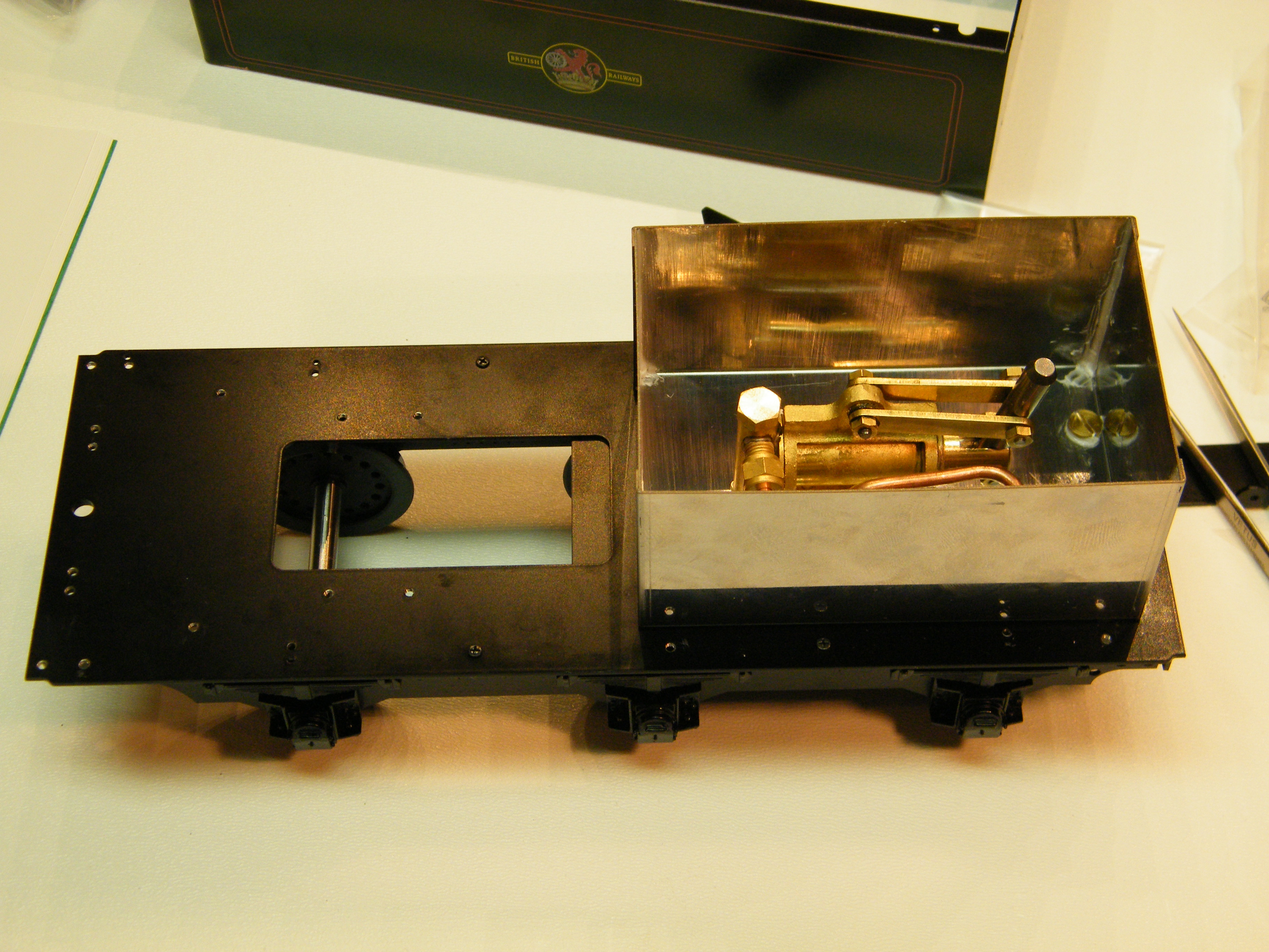
Top view with fuel tank removed showing fuel sump:

Complex brake rigging (faux):


The tender is functional and contains both the alcohol fuel and water. There is a hand pump under the cover on the rear deck to fill the boiler. The loco has an axle pump to keep the boiler level up as she runs. The front portion of the tender contains the fuel tank which feeds a triple wick burner, the wicks being around 12mm diameter, each having some 30 wick strands. The burner is force draughted in proper locomotive fashion by the hot gases being drawn through the two boiler flues (that contain superheater elements) by a miniaturised Lemaître style multiple jet exhaust ejector, albeit having 4 pinholes instead of the five 2.5 inch diameter jets that the full size loco is equipped with. This is not a toy, it is truly a miniature locomotive.
Moving on to the loco, the starting point is with the cylinders. To lap the machine marks off the valve and corresponding cylinder faces. A sheet of 1000 grit wet and dry is provided:

The 80 lb surface plate lives on top of my woofer under the CD player! It stays there too, I now avoid lifting such things alone though the CD player is also 80 lb! The amp next to it weighs around 250 lb, I am glad I made it so that the power supply and amp can be separated, it can also be rolled over forwards on the lexan side plates to permit access if needed.

OK, getting back on track as it were, here are the components for the middle cylinder with a completed outside cylinder. A slide valve can be see at top left with it’s steam chest at the centre bottom:

Completed outside cylinders and middle cylinder components with small bottle of steam oil:

Complete middle cylinder with crosshead and slidebars:

Herewith the crank axle (in this case, the middle axle) and eccentric for the inside cylinder valve:

I forgot to photograph the assembly of the frames that are held together and apart by members called stretchers. The instructions admonish the builder to take great care to ensure that the frames are aligned to each other properly, I used the surface plate shown in the cylinder/valve lapping process above to do this.
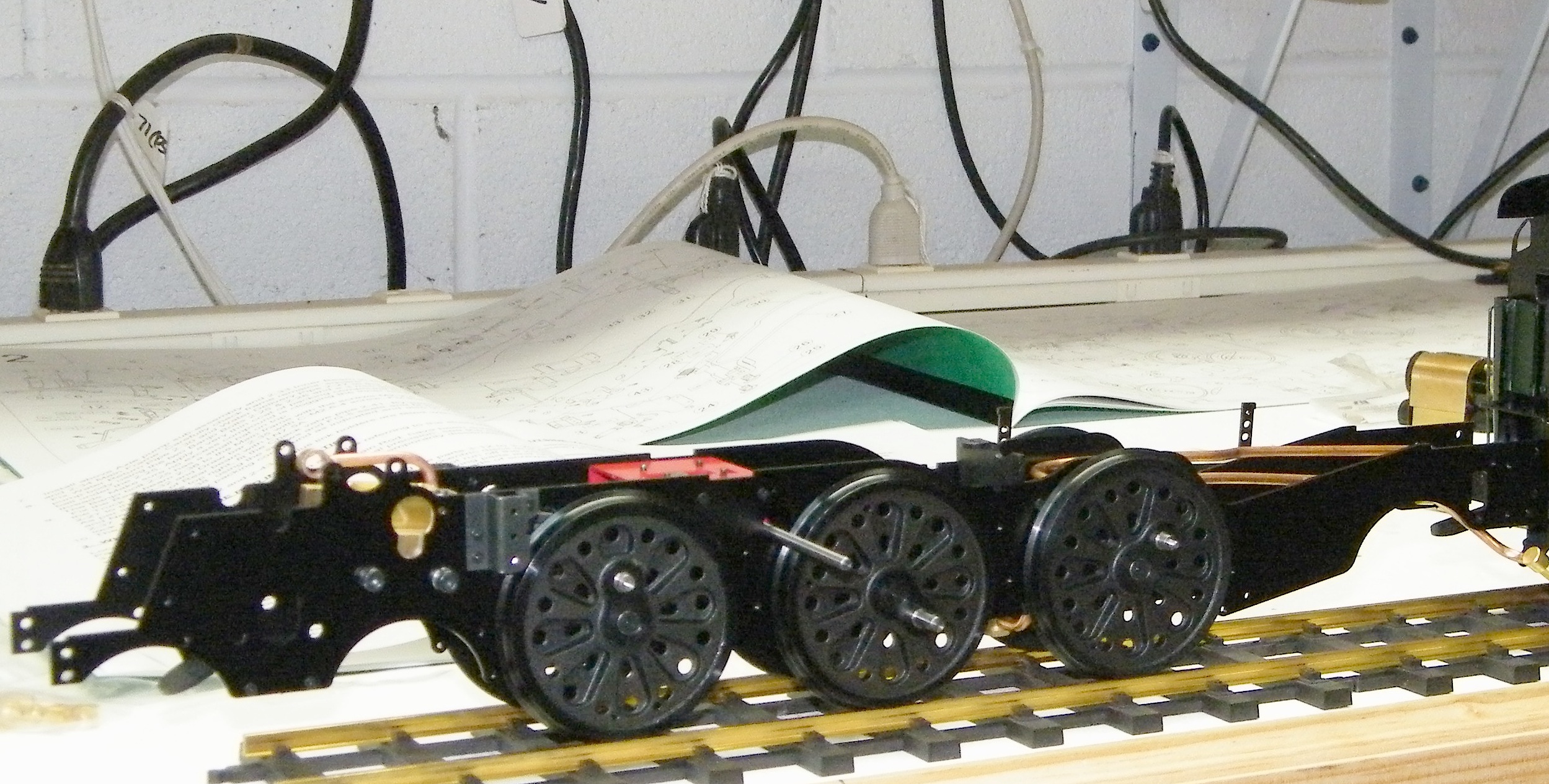
Here are the frames and wheels:
Steam valve gear is designed to allow the relative phase of the piston and valve motion to be shifted by 180° to permit reversing. The mechanism that does this also allows the percentage of the piston stroke at which steam admission is cut off to be varied so that as the loco gains speed, it can be “notched up” resulting in the steam being used more expansively. Various forms of this mechanism have been around since 1841, the earliest being called Stephenson’s valve gear but of course, it was not invented by him (a precedent for Edison I suppose). Belgium Engineer Egide Walschaerts came along with his mechanism in 1844, and it became the most common locomotive valve gear up until the end of steam on railways. The major component of both gears is the expansion link that oscillates back and forth with the rotation of the wheels. The link carries a die block that may be slid under driver control from one end of the link to the other to obtain variable cut off and reversing. In the case of Walschaerts, the expansion link provides one component of the valve motion via the die block and radius rod, the other component being derived directly from the piston rod, the two motions being combined at the valve spindle by amazingly, a combination lever! Whodathunkit? Stephenson’s gear also combines two motion components but differently, both being derived directly by eccentrics on the axle. (Don’t you just hate it when you get eccentrics on the axle?) Interestingly, the two motions sum to a somewhat square characteristic so that the valve opens quickly, slows while open and then closes quickly which is quite clever, especially when you consider just how long ago all this was thought out. It makes all the variable valve timing hoopla for cars seem somewhat less extraordinary.
Here is one expansion link with radius rod and die blot in the slot. The two plates sandwich the link/radius rod/die block and have trunnions on which the expansion link swings. The elbow connects to the rod that provides motion from a flycrank mounted on the end of the driving wheel axle. The slot in the radius rod carries a bearing on the end of the reverser lifting arm that allows the rod to move back and forth while being held at the required position in the expansion link.

Here it is assembled:

Here is a picture of the left side motion assembled. The flycrank on the rear driving wheel is where the speedometer drive is located, of course faux at this scale!

Here are the three cylinders installed in the frames complete with the middle valve gear, the pipes fitted so far are for exhaust. All three cylinders drive the middle axle. The shaft, sometimes referred to as a weigh shaft, will carry the three reverser lifting arms so that as the reverser is operated, all three die blocks and radius rods are moved together to the required setting. I made a point of drilling a small indent into the shaft where the locking screw for the middle reverser lifting arm engages since it will be hard to access later if it moves. The outside ones can be adjusted relative to the middle one during valve setting. I locked all the motion screws using 222 Loctite, that can be undone if needed. In particular, it is essential to ensure that the cross heads are securely screwed home on the pistons shafts, ditto the valve couplings.

Talking about valve setting, the point is to first align all the reverser lifting arms at the centre, then set the valve slides on the valve rods such that the port openings are equal at both ends of the cylinders and to do this in both forward and reverse gear. (Having the centre axle solid mounted as it is, must help this procedure.) The instructions suggest that if perfect settings cannot be obtained in both forward and reverse gear, to make the forward setting “perfect”. I did have to do that though the reverse settings are still very close to equal. Quite good.
Here, I have fitted the plumbing ready for an air test of the motion. The superheater and four jet exhaust nozzle are clearly visible:

This picture shows the drive system on the rolling road ready for an air test (that was successful). The stainless steel tubes are the super heaters that will later live inside each boiler flue. A fitting is attached where the steam outlet from the boiler would be to allow an air line to be connected. The two U shaped tubes at the front are connected to a displacement oiler. The oiler works (hopefully) by allowing steam to pass down one tube into the oiler where it condenses forming water that pushes the oil up into the other tube. If the top of the smoke box isn’t oily after running, there is reason to take a close look to ensure no blockages!

Superheater and manifold:
While we are on the motion, here is the underside much further along also showing the combustion chamber. The bogie with it’s side control spring and rear pony truck are fitted too. The axle boiler feed pump is between the centre and rear drivers, driven from an eccentric (the buggers get everywhere don’t they) on the front axle.

Now to the boiler, here we have the two superheater elements partially inserted into the boiler flues. The inclusion of a superheater is good news. Heating the steam out of contact with the water makes a lot more work available, furthermore, it saves wasting a lot of the fuel in getting the cylinders hot enough to prevent stalling on condensing saturated steam. Having some experience of small locos that do not have superheaters and having done three steam tests on the rolling road, I can attest that this scheme is much more than cosmetic!

Here is the combustion chamber showing two water tubes that sit in the rather fierce flame from the three large wicks. The flame is sucked around the back of the boiler and into the flues. The chamber is fully lined with ceramic insulation cloth. When the loco is getting up steam using it’s own blower, (steam nozzles located in the exhaust ejector) the flame almost howls! It raises steam VERY quickly. The steam blower is effective from roughly 2 bar (29 psi), half full operating pressure. Below that, it is necessary to use a heat resistant suction fan inserted in the chimney. I used a hand vacuum cleaner run from a variac with a couple of feet of copper tube from the chimney. I also drilled large holes into the tube to permit cooling air to be drawn in, also I used a box fan to blow the fumes outside. It works very well but I do not recommend it, the vacuum still got very hot and smelly, the fumes are most likely toxic too.

Here is the completed boiler, note the water level gauge glass. The long lever is the steam regulator and the small lever behind the regulator is for the steam blower:

Here, I am trying the boiler in it’s shroud, onto the frames. (It may be helpful to cut up a detergent bottle and make a thin plastic sleeve the guide the boiler into the shroud.) It took many tries to get everything aligned properly! If you look carefully, you can just see the water feed to the boiler between the rearmost driving wheel and the boiler. Getting this bend right was tricky, there is barely enough room to sneak between the corner of the combustion chamber and the wheel. The pipe as made had the correct curve shape but it was in the wrong place! I annealed the copper to get the bend out and reformed it where it needed to be. I have attempted to illustrate this in the problems area at the end of this narrative.

Here is a view of the multiple jet exhaust nozzle and the end of the boiler flues. The two longer jets are for the steam blower that is used to force the draught when the loco is stationary, the pipe emerging from the boiler feeds the blower jets and is controlled by a valve on the back-head. The top spigot is the steam delivery union from the regulator.

I forgot to take pictures of the smokebox construction however, I did find it necessary to open the smokebox after some runs. You can see the outside of the exhaust ejector venturi. The small pipes are for the lubricator.

To see it steaming, click on this.
Words to the wise on steam testing. Watch the water glass constantly to ensure that the axle pump is working. If water does not come out when you open the bypass valve, the pump is not working. For the first test at least, leave the return water connection off so you can see the return water flow. WATCH THE LEVEL IN THE TENDER! It gets through water surprisingly fast.
I did something VERY stupid. The fuel tank dispenses the fuel into an open well under the tender. There is a tube with a slant cut end that dips about half way down into the well and a needle valve opening in the bottom of the tank that lets the fuel run into the well. It maintains a constant level because when the fuel covers the end of the cut tube, no air is admitted to the tank, cutting the flow off IF YOU REMEMBER TO FIT THE FUEL CAP! I forgot on the second run and wound up with a nasty fire. I can’t smell wood alcohol* and it is hard to see alcohol burning until it has set something else alight! In mitigation, I did have a soaking wet towel ready and that saved the day, snuffing the fire out instantly with no mess. As with a frying pan fire, there is NOTHING to beat a wet towel. I am so glad that I knew this and maybe these words will save somebody else’s pride and joy.
*The British use methylated spirit that has a strong smell and is coloured purple. Very sensible.
Problems encountered.
Many components required significant filing to make them fit without forcing, certainly more than simply removing paint here and there.
One expansion link hanger was bent such that it was unusable, here is a picture showing the other side hanger for comparison. I held my breath and carefully bent it straight. Fortunately, the (lost wax) cast parts are brass, both tough and malleable!

Regarding the incorrectly formed water feed pipe, here is a picture showing the bend. You may spot the slight crinkles where the bend was and the pen mark I made to relocate the bend to sneak between the frame and the corner of the combustion chamber. The front corners of the combustion chamber are very close to where the frames rise over the rear horns and it’s width almost occupies the space between the frames making the fit very right. I studied things for quite a while before seeing how to relocate the bend because it is hard to see what’s so with the boiler in place, yet that is what must be accommodated!

All three reverser lifting cranks have forks that fit around the slot in each radius rod, these were all distorted such that I had to carefully tweak them open.
A much more serious problem had to do with the driving wheels. The centre wheels have no suspension by design. The front and rear driving wheels do have horn blocks and springs. I found that the centre wheels were barely touching the rails with the front and rear horn blocks topped out. I checked this by removing the springs and put engineer’s blue at the top of each horn. Sure enough, the centre wheels still barely made contact and there were two blue witness marks left on the top of each horn block. I carefully filed 20 mil (I trained as a toolmaker so precision filing is a skill that I have) off the top of each horn block. By the way, “mil” is NOT an abbreviation for millimeter, it is a correct term for 1 thousandth of an inch!
I found it necessary to work on the expansion link assemblies quite a bit, beyond the lapping of the inside surfaces per the instructions. I found it necessary to shim one pair of expansion link plates further apart, I use paper which provided a small by necessary increase of 2.5 mil. Here is the link with paper shims:

I also found it necessary to reduce the length of the die block pin on one radius rod, the pin was slightly proud of the die block causing the reversing action to balk, here it is after filing the pin down slightly:

I found that one connecting rod was fouling the underside of a slide bar. The lower slide bars are unfinished lost wax castings and looking carefully, I could see that one end was quite a bit thicker than the other causing the screw that secures it to project too far. Simply reversing the bar solved the problem.
Try to test the action of the axle pump when you do the air test, it is imperative that this works properly. I had a bit of a panic when I realised that the water had disappeared below the bottom of the gauge glass during the first steam test! The action of the inlet check ball must be correct and the clearance for it can be adjusted using the fibre washers. For the most part, I don’t use fibre washers, preferring metal to metal plus a smear of sealant so I had things too tight. David Stick speaks to this issue in his expert narrative:
Here is a narrative on building this model that I found very helpful:
I’m OK with these issues, I enjoyed the fitting challenge but the price of the kit at $5600 led me to expect better.
The vendor seems to think that no significant filing is necessary. I’m not clumsy or stupid, it was necessary. Interestingly, one area of fit that seems to have troubled many, the running boards, was not a problem for me. However, one of the lost wax cast steps up to the running board did need significant filing to fit. Oh, there is a hole on the frame side of both steps that does not align with the corresponding hole in the frames at all, they are only visible on very close scrutiny and contribute little if anything to the structure so I simply omitted the screws that are intended to be fitted. More than one experienced kit builder has suggested that Aster did not have such quality issues until they came out with the rebuilt Merchant Navy kit. The diagrams that come with the instructions are superb. The instructions need careful review. In many places, the order of assembly simply doesn’t work. I did not keep notes and I am not going to try to recall the details. Suffice it to say that trial assembly at every step is essential and it is well worth the effort! A handsome model indeed.

Update, 12/28/15. Since the boiler is of the forced draught type, it needs a device to create a draught until the steam pressure is sufficient to force the draught by blowing steam up the chimney venturi. These devices do not seem to be readily available. Aster Models UK sell them but they are quite expensive so I decided to see what I could cobble together. I have a 4 inch computer fan and I was concerned that the heat would be too much for it. So I fixed it to a plastic funnel, stuck it in the chimney and tried it. (Serendipitously, the funnel interfaces perfectly with the fan.) It worked just fine, even though aerodynamically speaking it is all wrong. I “should” be using a centrifugal blower. As you may expect, there was some melting of the pointy end of the funnel. It seemed to me that if I could fit a coupling onto the funnel that would sit snugly around the chimney rim rather than inside it, all would be OK. So a trip to Home Despot saw me with a PVC coupler and some copper fittings.

Here is a cut down funnel, a PVC coupler and a 1″ copper coupler. The copper coupler fits nicely around the rim of the chimney. I soldered a short length of 1″ copper tube into it to form a transition from the chimney rim to the funnel. The disc was cut from copper clad circuit board (using hole saws with suitable clamping) to form a centering device for the transition piece. The scollops in the PVC coupler were also formed using a hole saw, again with suitable clamping. I had no trouble with this operation, even though the hole saw centering drill was in fresh air, it went perfectly.

The copper transition piece was pushed into the funnel up to the abutment formed by the coupler. The PVC coupler fits the smokebox such that the flats rest on the smoke deflectors, this would ensure that the somewhat top-heavy contraption would sit solidly and not tend to fall off!
Here’s the resulting interface to the smokebox / chimney:

And here it is in place. The top of the funnel is just visible. I cut out a plywood flange to fit behind the rim of the funnel which allowed me to clamp the fan to the funnel. All the joints were made using silicone sealant hence the messy appearance. I took advantage of the annular chamber formed by the pvc coupler around the copper transition piece to fill it with water and made a tiny pressure relief hole into the funnel. This way, the highest temperature that can communicate to the funnel is the boiling point of water. Having tested the complete device, this precaution seems to be unnecessary. It works very nicely, providing just enough draught to make lighting up easy and steam is raised in about 3 to 3 1/2 minutes. The loco blower can take over at 50% pressure (2 bar). I will finish it by fitting a Ni-mH battery pack.
