HP 425A Micro Volt – Ammeter
I keep opening my posts with something like “this is an interesting _____” and so it is. An instrument that is designed to measure from 10 μV to 1 V and 10 pA to 3 mA has little if any practical value to me, yet it is of interest. I had never given the issue of measuring such low electrical values any real thought and the design of this instrument is completely new to me.
I must preface the following attempt to describe the operation of this instrument by saying (as I have said before) that I am an M.E. and asked my friend Kenneth Kuhn http://www.kennethkuhn.com/hpmuseum/ to straighten me out which he kindly did and any errors are due to my failure to correctly transcribe his explanation:
HP in their manual have this to say, “If the 425A is considered a black box with two input and two output terminals, it is a DC amplifier”. If the amplifier were DC coupled, any drift or DC offsets in the amplifier would swamp the extremely small signal. The system uses lamps acting on photoresistors through a chopper wheel to modulate the incoming DC signal so as to present an AC signal to the AC coupled amplifier, the signal is then demodulated to restore the DC.
The output of the modulator is a rough squarewave having an amplitude proportional to the applied DC signal. The chop or modulation frequency is 5/6 of the line frequency to ensure that line noise is not passed, (50 Hz is not monotonically related to 60Hz.) The resulting AC signal is amplified by an amplifier that has a 50 Hz reject T filter in the negative feedback path thereby causing it to respond extremely strongly to the 50 Hz signal and not much else. This greatly amplified signal is next demodulated by a second light chopper that is synchronized to the modulator by virtue of using the diametrically opposite side of the same chopper wheel. A 50 Hz reject T filter removes any residual modulation resulting in a clean DC signal proportional to the input, that is applied via a cathode follower to the meter.
Kenneth also pointed out that that specialized op. amps having zero dc offset, known as commutating auto-zero amps, are available. What used to take a motor and chopper wheel is now packed in an integrated circuit. I suppose that is progress but not as much fun!
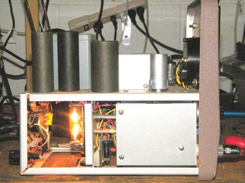
The modulator lamps and the light pipes to the photocells are visible above.
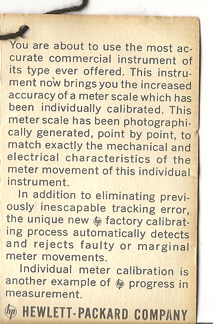
These instruments featured individually photo-calibrated meters and the original tag is still with this one:
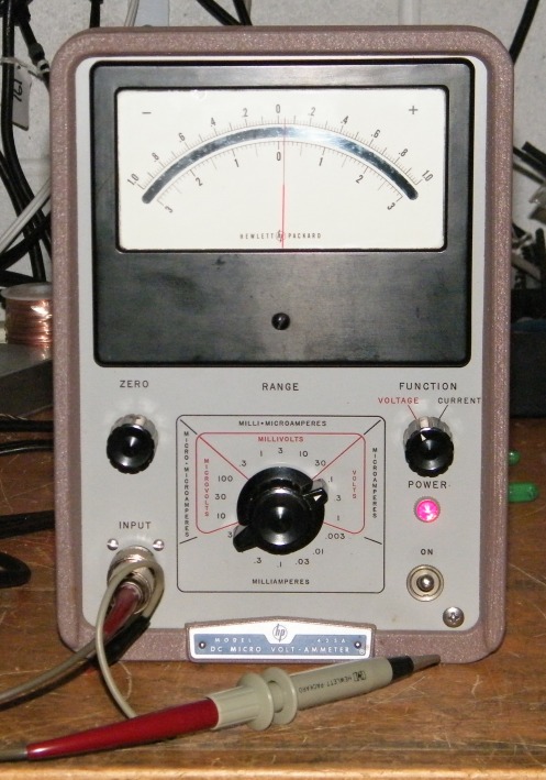
I also have the proper probe for it, shown with the unit in the top picture.
The unit arrived in excellent condition. The meter glass was loose due to the retaining clips having fallen out. Actually getting the bezel off was a little tricky since it had been secured using brass break-off head screws, presumably to protect the special calibration. I managed to grasp each one using hemostats and got them all out without any unwanted adventure. I cleaned the glass (but NOT the meter face) and re-tensioned each clip and put a little glue on each also. The chopper bulbs were not burning consistently due to corrosion on the pins, another job for Deoxit. It then worked and applying a DC source set to plus and then minus 0.5000 on my HP 3468A, the meter showed precisely + and – 0.5. My next job may be to construct a precision DC voltage source using something like a GR decade box as a precision divider. It will be powered by batteries for quietness, if, if I do the job!
There are a couple of unusual considerations when using a DC meter of such high sensitivity:
Galvanic and thermoelectric effect between the probe and the terminals of interest. (I have in the past been puzzled by a DC shift on a HP 122A scope that turned out to be a galvanic issue. That one took some lateral thinking on my part to identify.) Also noted in the manual is the possibility of seeing triboelectric effects due to flexing of coaxial cables.
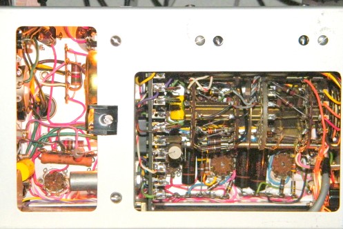
Here is the other side showing the rather daunting range switch:
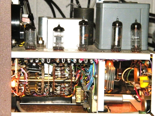
Here is the underside also showing the range switch:
Very interesting read. Thank you very much again for sharing your experience and knowledge.
Hi Lars.
Thank you. I remain happily surprised by the level of interest shown in this esoteric hobby. It is true to say that without the internet, it would be very isolated and hermit-like, being able to share my adventures is what makes it the most fun!
I was cleaning out my garage and figuring out what to keep and what not, and found this picoammeter on the shelf (knew it was there) and decided to power it up. The meter was stuck so I took it apart and cleaned it so that it is working properly. However, the unit does not appear to function when powered up. I was curious about the lamps and the whirring motor. Knowing the high sensitivity of the instrument, it was obvious that this was a strobe for a chopper amp. Pretty creative for that era.
Hi Doug.
Have you followed my narrative on what was necessary to get the unit I have working properly?
You say “creative for that era”, well “that era” (and before) was extremely creative. I find myself thinking that maybe you meant pretty advanced for that era?
Best
Richard
Excellent write-up! My own 425A works great, a nice tool for checking capacitor leakage. Unfortunately, mine came without the probe and I’m having trouble finding a substitute for the probe’s triaxial N connector.